Author Topic: MPPT progress  (Read 1255 times)

0 Members and 1 Guest are viewing this topic.

commanda

  • Hero Member
  • *****
  • Posts: 731
MPPT progress
« on: November 25, 2007, 02:26:56 AM »
Quite some time ago, I got my hands on a commercial switchmode power supply, 24 volts at 20 amps.
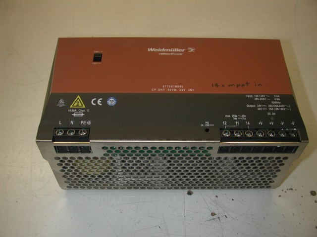


I then proceeded to modify it so the output voltage could be controlled by an external source. I cut one track on the pcb to free up one screw terminal, and hung a resistor from the voltage control op-amp input to this external terminal.
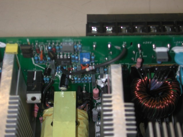


Some figures;


unmodified, the internal adjustment pot gives an output range of 22.44 to 29.17 volts.

setting the internal pot to minimum, and using a bench power supply to drive the new mppt input terminal;


control       output

volts         volts


  1. 0           20.85
  2. 0          27.25
  3. 0          28.50


This particular power supply probably won't be used much beyond some initial testing. Reason is the input voltage range is too small. Spec sheet says 250-370 volts DC.


However,the latest Soanar catalog landed on my desk last week. They have a similar supply with an input range of 124 to 370 volts dc.


Using a 6U rack panel blank, I then mounted all the bits and wired most of it up.
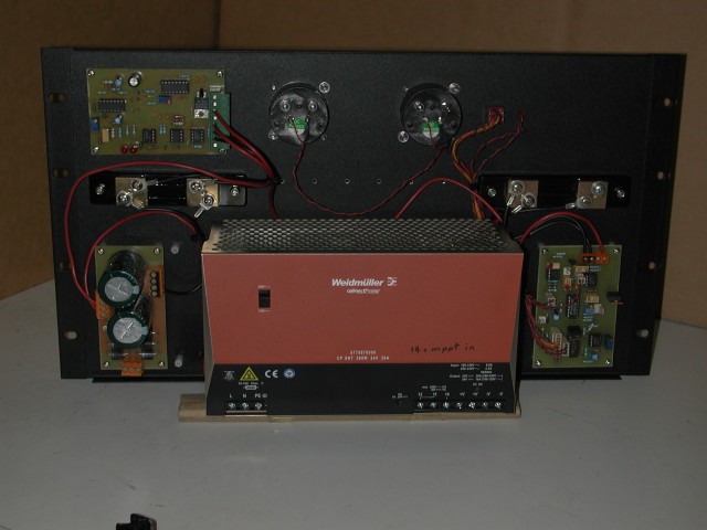


Starting from the bottom left and going clockwise, we have the 3 phase rectifier board; immediately above this is the input current shunt, which feeds the mppt board immediately above it (top right). Top centre are 2 meters, one for rpm and one for output current. Just to the right of these is the star-delta manual over-ride switch with its 2 leds. Bottom right is the metering board, with the output current shunt just above it. There's a row of holes below the meters to mount 4mm banana sockets for test points.


I did do a block wiring diagram in pencil, but it didn't scan too good. I'll do a better one later.


Next weekend I'm gonna put the F&P back in the drill press and start powering this thing for real. After I modify the mppt board so the output control signal is the right polarity to control this psu.


Amanda

« Last Edit: November 25, 2007, 02:26:56 AM by (unknown) »

bigkahoonaa

  • Jr. Member
  • **
  • Posts: 57
Re: MPPT progress
« Reply #1 on: November 24, 2007, 11:14:02 PM »
Nice unit Amanda, neat layout.
« Last Edit: November 24, 2007, 11:14:02 PM by bigkahoonaa »

Flux

  • Super Hero Member Plus
  • *******
  • Posts: 6275
Re: MPPT progress
« Reply #2 on: November 25, 2007, 01:30:34 AM »
I am looking forward to your results.

Even that voltage range should make a big improvement . At the low output end you may well be able to go below the makers claimed  250v as long as any internal supplies don't drop out, they had to guarantee full output at the low limit, you will only be asking for a small percentage at that level.


Flux

« Last Edit: November 25, 2007, 01:30:34 AM by Flux »

dinges

  • Hero Member
  • *****
  • Posts: 1294
  • Country: nl
Re: MPPT progress
« Reply #3 on: November 25, 2007, 07:57:11 AM »
Looking good.


I'm surprized that the single resistor was all it took to increase the voltage range. Apparently there's no over voltage protection in it (or at least it doesn't kick in).


You could try measuring the input voltage range using a Variac. Testing a PC PSU, I found that it worked full output power from 140-260+ Vac and with reduced power down to 50Vac. However, it needed at least 110Vac to start.


You may want to try a similar test on your present PSU, as it may perform better w.r.t. input voltage than you may suspect.


I'm sure I'm not the only one who will follow your progress with this project.


Peter.

« Last Edit: November 25, 2007, 07:57:11 AM by dinges »
“Research is what I'm doing when I don't know what I'm doing.” (W. von Braun)