Author Topic: Spice Circuit Analysis  (Read 8241 times)

0 Members and 1 Guest are viewing this topic.

SparWeb

  • Global Moderator
  • Super Hero Member Plus
  • *****
  • Posts: 5452
  • Country: ca
    • Wind Turbine Project Field Notes
Spice Circuit Analysis
« on: November 29, 2007, 04:20:36 AM »
I have an interesting discovery to share, for those who like software.


When I heard about Spice, I thought it was just for electronics.  I just tried the software out, and it turns out that I can create models of the generator-rectifer-battery system without too much difficulty.


With Spice, I first created three sources of voltage, and that was tricky to set up at first, until I understood what the program was doing.  In the schematics I've posted below, I have the generator shown as three 20V (peak) voltage sources, with a 20Hz frequency and they are 120 degrees out of phase with each other.  (You have to figure out the time lag, not the phase angle, to get the phases to work).
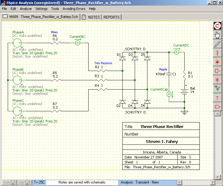


Next I layed out the set of six identical rectifiers.  I picked "Schottky" diodes, but any type will work, and I think the generic bridge you can buy at the hobby store is just silicon.  Changing the diode type seems to make no difference in the results.


The battery had me confused for a while until I added a resistance in series.  Now I've come to understand that the resistance in the model is the resistance inside the battery.  This also changes with the battery's state of charge, so it's a tricky quantity to get a hold of.  I just found a value by trial and error that works for the sake of this example.


Later, after getting the basics to work, I started adding things like the "trimming" resistors and Wire resistance.  These are resistance values in my own system.  The trim resistors are necessary on my setup or the blades of my windmill would stall in light winds.  


For fun, I later added a little filter capacitor across the battery.  I've heard that you can take out "ripple" in the charging current, and here's a way to see that, and play around with it.


In several places on the schematic you can see the green Current sensors.  When the schematic is complete, these icons control the way Spice solves its formulas.  The current solutions are shown in graphs on a separate page.
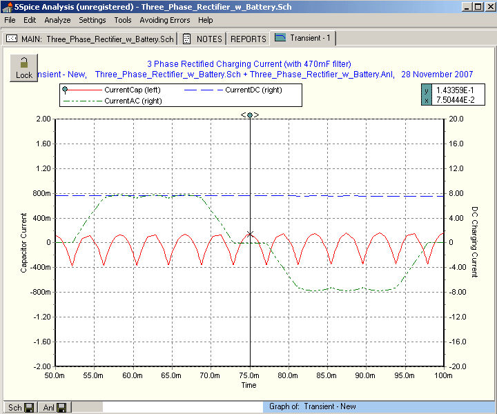


Now that I have some results, I can see several things going on:

The charging current is about 8 Amps.  That's not too different from what you would get if you calculated it by hand:


20V / 1.73 = 11.5V rms

(11.5V - 0.7V) / (0.2ohm + 1ohm + 0.1 ohm) = 8.3 A


There is a spiky current going through the capacitor.  It's taking the ripple instead of the battery.  If this is a good thing, then this software can help you size up the capacitor.


The AC waveform is a chopped sine (just like Flux says it does).  The AC has a ripple at 12x the phase frequency.  I thought there would only be 6.  The 470 mF capacitor is soaking up almost all of the ripple, about 0.2 Ampere AC with a frequency of 240 Hz.


Later, I changed the value of the capacitor from 470 milliF to 470 nanoF, and saw the result is that much less ripple is soaked up by the capacitor.
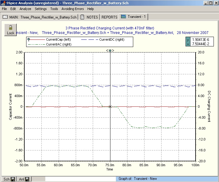


Although I can't say yet what's good or bad, this is an example of how you can use the simulation to experiment with values of the components and see the result.  


Some other things to point out:

The graph puts time on the lower axis.  I picked 50 msec to 100 msec to represent one complete cycle (at 20Hz).  

The first cycle is a little imbalanced.  Maybe there's something I can learn in that, but for now I ignore it to see the more stable second cycle.


If you're interested enough to try Spice for yourself - warning: start simple!  I tried laying out the whole shebang at once and I just wasn't getting anywhere.  I eventually went right back to basics:  1 DC battery, 1 resistor, and 2 wires, just so that I could learn to "talk" Spice's language.  Then worked up, slowly, from there.


The analysis to use for the generator system is the Spice "Transient" analysis.  The Spice "AC" analysis doesn't seem to do anything, and obviously a "DC" analysis isn't appropriate to this system.  With this in mind, you must set up the generator's voltage sources under the Transient tab, not the AC tab.  (Took me 2 hours to figure that out)


Well I can go on and on (I already have) but I'm posting this really to share this neat tool.


For those still reading...    http://www.5spice.com


Steven

« Last Edit: November 29, 2007, 04:20:36 AM by (unknown) »
No one believes the theory except the one who developed it. Everyone believes the experiment except the one who ran it.
System spec: 135w BP multicrystalline panels, Xantrex C40, DIY 10ft (3m) diameter wind turbine, Tri-Star TS60, 800AH x 24V AGM Battery, Xantrex SW4024
www.sparweb.ca

Flux

  • Super Hero Member Plus
  • *******
  • Posts: 6275
Re: Spice Circuit Analysis
« Reply #1 on: November 29, 2007, 01:21:05 AM »
Interesting.

I am not sure how the simulator sees a battery. The simulator is seeing the emf, but I don't know why you need to add a series resistance. That is fooling things and causing you to see a ripple above the battery emf.


The real internal resistance of a battery is very small and can be neglected for charging circuits. It may be that the simulator is confused about what to do with the power component of the charging.


Try using a zener diode in place of the battery, it may make more sense to the simulator. You can add a capacitor across the zener, but it may not be necessary unless the zener simulation includes slope resistance.


To the rectifier the battery looks much like an infinite capacitor with a minute series resistance loaded with a diversion controller maintaining constant voltage.


Adding significant series resistance causes you to see voltage ripple above the emf and also makes the whole thing go wrong when you change the charging current.


There will be a 6 pulse current ripple but you should see negligible voltage ripple across a battery if you get the simulation right.


I am sure the simulator can do it, but you may need to experiment for the battery model.


Having a significant internal resistance in the battery model will not let you see the true effect of any series line resistance as that should be external to the battery.


Most of what you have produced makes sense, I am sure there is a way to make it even more useful.


Flux

« Last Edit: November 29, 2007, 01:21:05 AM by Flux »

DamonHD

  • Administrator
  • Super Hero Member Plus
  • *****
  • Posts: 4127
  • Country: gb
    • Earth Notes
Re: Spice Circuit Analysis
« Reply #2 on: November 29, 2007, 01:45:33 AM »
These SPICE-type tools can be fabulous.  Apparently the XCircuit tool I'm now using for my layouts is capable of exporting to SPICE or something similar, though I've only been  making the layouts visually correct for now.


Maybe you can find on the Net a SPICE plugin that simulates a lead-acid battery properly.  As you say, it's a complex beast, and someone else might have done all the work for you already.


Rgds


Damon

« Last Edit: November 29, 2007, 01:45:33 AM by DamonHD »
Podcast: https://www.earth.org.uk/SECTION_podcast.html

@DamonHD@mastodon.social

tecker

  • SuperHero Member
  • ******
  • Posts: 2183
Re: Spice Circuit Analysis
« Reply #3 on: November 29, 2007, 06:38:58 AM »
Maybe a  reactive  impeadance
« Last Edit: November 29, 2007, 06:38:58 AM by tecker »

scottsAI

  • Hero Member
  • *****
  • Posts: 884
Re: Spice Circuit Analysis
« Reply #4 on: November 29, 2007, 10:22:56 AM »
Good idea DamonHD,


Limited models out there, both in their number and what they model.

http://www.spectrum-soft.com/news/spring2007/battery.shtm

Designed for discharge, work needed for charging simulation.

Link to original model from EDN does both?:

http://www.edn.com/reg/download/files/ftptop/edn/di_sig/tu436z.zip


Pspice Battery model added in 2005, you may already have it!

The Capture-PSpice flow has been enhanced to provide support for simulating battery

models. Two new models, awblead_battery and awbflooded_battery, have been

added. To instantiate battery models in your Capture design, select Flooded or Lead_Acid

from pspice_elem.olb. Using these models you can now accurately model electrical

characteristics of a lead-acid battery during discharge over a large range of operating

conditions. The parameters passed to these models are state of charge of the battery,

ampere-hour, and open circuit voltage across the battery.

To know more about battery model, see PSpice Reference Guide.


Have fun,

Scott.

« Last Edit: November 29, 2007, 10:22:56 AM by scottsAI »

SparWeb

  • Global Moderator
  • Super Hero Member Plus
  • *****
  • Posts: 5452
  • Country: ca
    • Wind Turbine Project Field Notes
Re: Spice Circuit Analysis
« Reply #5 on: November 29, 2007, 10:43:13 AM »
I think the simulation puts only a microscopic resistance in a battery by default.

When you set the resistance to zero, the current through the battery jumps to near infinity.  Only the 1 milliOhm resistance in the battery prevents the current from being truly infinite, and now we're talking about a computer program avoiding a divide-by-zero error, not about what's realistic in a simulation.


But a real battery affects the current depending on its state of charge.  That's not built in, so maybe some searching around will turn up a way to "fool" Spice into modelling a specific battery's charging behaviour.


Anyhow, "close enough" counts for some questions.  Last night I tried changing the battery voltage, and then used various levels of EMF to see how the DC current was affected.  The ripple also got stronger.  There were several other effects, and I think that phony R in series with the battery, again, is affecting things.

« Last Edit: November 29, 2007, 10:43:13 AM by SparWeb »
No one believes the theory except the one who developed it. Everyone believes the experiment except the one who ran it.
System spec: 135w BP multicrystalline panels, Xantrex C40, DIY 10ft (3m) diameter wind turbine, Tri-Star TS60, 800AH x 24V AGM Battery, Xantrex SW4024
www.sparweb.ca

scottsAI

  • Hero Member
  • *****
  • Posts: 884
Re: Spice Circuit Analysis
« Reply #6 on: November 29, 2007, 11:15:48 AM »
Hello SparWeb,


Welcome to my world, I drew up a nearly identical circuit coupe years ago. I grounded the AC side vs the battery as you did. Same results. From this simulation I realized the PMA's limitations.


The current should have ripples, that is how it comes from the generator!-)

The filter capacitor across the battery adds little value. If the rectifier is removed from the battery then a cap is a good idea, not to filter the current into the battery. The battery is a HUGE cap, by adding a relatively small cap in parallel gains nothing.


As Flux said, the battery internal resistance is small the 0.1 ohms shown is too large. (unless a few ah battery) With that said, a long wire run from the generator can add that much or more. I will lump the various resistance at one point assuming there are no effects from something else. If you add an inductor as the wiring this will show the benefit of the cap at the rectifiers. Open loop wire is 3nH / ft of dual conductor wire. Does not sound like much but 100 foot it adds up, plus the current is dozens of amps, so a voltage spike is possible from it at the rectifier and any switches in circuit.


Simulation of the generators resistance you can see how much power is dissipated as heat. The problems of cooking the stator while furling is very real, shutting wind mill down at furling speeds is dangerous. When the wind is stronger than the generator shorting output will destroy it.


Have fun,

Scott.

« Last Edit: November 29, 2007, 11:15:48 AM by scottsAI »

Flux

  • Super Hero Member Plus
  • *******
  • Posts: 6275
Re: Spice Circuit Analysis
« Reply #7 on: November 29, 2007, 11:50:33 AM »
Yes putting zero will probably confuse it. One milliohm would seem a reasonable value.


I think you handle state of charge by changing the emf not by trying to increase series resistance. The external resistance to the battery from the alternator or from the line Will force the thing to give sensible currents. State of charge just alters the ratio of battery emf (nominal volts) to alternator emf ( open circuit volts).


The change of voltage of a battery with state of charge is mainly a function of the difference caused by the chemical change and also the polarising effect of the gas on the plates that causes the surface charge. The true internal resistance mostly accounts for the change in voltage with load during discharge after sufficient load has been applied to remove surface charge. For a typical battery it will be very small and negligible to normal charging currents.


The true internal resistance is likely to be the thing that decides how the simulator handles the ripple, if you use a suitable value for internal resistance then the voltage ripple may go away without adding a capacitor, but adding 1 farad would likely simulate the way a battery looks to a charging circuit.


Flux

« Last Edit: November 29, 2007, 11:50:33 AM by Flux »

SparWeb

  • Global Moderator
  • Super Hero Member Plus
  • *****
  • Posts: 5452
  • Country: ca
    • Wind Turbine Project Field Notes
Re: Spice Circuit Analysis
« Reply #8 on: November 29, 2007, 01:06:14 PM »
Thanks for the lead, Scott.

The links didn't work, but they were a good start.  With a little digging, I found an FTP site (in France!) with some tools on it.  I'll give them a try and report back...

« Last Edit: November 29, 2007, 01:06:14 PM by SparWeb »
No one believes the theory except the one who developed it. Everyone believes the experiment except the one who ran it.
System spec: 135w BP multicrystalline panels, Xantrex C40, DIY 10ft (3m) diameter wind turbine, Tri-Star TS60, 800AH x 24V AGM Battery, Xantrex SW4024
www.sparweb.ca

Ungrounded Lightning Rod

  • SuperHero Member
  • ******
  • Posts: 2865
Re: Spice Circuit Analysis
« Reply #9 on: November 29, 2007, 08:41:27 PM »
I think the simulation puts only a microscopic resistance in a battery by default.

When you set the resistance to zero, the current through the battery jumps to near infinity.  Only the 1 milliOhm resistance in the battery prevents the current from being truly infinite, and now we're talking about a computer program avoiding a divide-by-zero error, not about what's realistic in a simulation.


Part of your problem is that you're doing a decent model of the generator's induced voltage but your model for the coil resistance is far too low.  Bump the coil resistance up to something sane and you'll be able to reduce the battery resistance to something approximating the very low resistance of the real battery.


You'll have to check the spice model documentation to see if it includes terms for state-of-charge, temperature, surface effects from charge rate, etc.

« Last Edit: November 29, 2007, 08:41:27 PM by Ungrounded Lightning Rod »

SparWeb

  • Global Moderator
  • Super Hero Member Plus
  • *****
  • Posts: 5452
  • Country: ca
    • Wind Turbine Project Field Notes
Re: Spice Circuit Analysis
« Reply #10 on: November 30, 2007, 08:30:51 AM »
Actually, there is no resistance modeled with the generators' coils.  The 0.2 Ohm resistors are the wires in the tower...


But that's not a bad thought.  The phase resistance of this motor conversion is 2.3 Ohms or so (I have the measurement written down somewhere).


Sounds like something that should be in there, though.

« Last Edit: November 30, 2007, 08:30:51 AM by SparWeb »
No one believes the theory except the one who developed it. Everyone believes the experiment except the one who ran it.
System spec: 135w BP multicrystalline panels, Xantrex C40, DIY 10ft (3m) diameter wind turbine, Tri-Star TS60, 800AH x 24V AGM Battery, Xantrex SW4024
www.sparweb.ca

SparWeb

  • Global Moderator
  • Super Hero Member Plus
  • *****
  • Posts: 5452
  • Country: ca
    • Wind Turbine Project Field Notes
Re: Spice Circuit Analysis
« Reply #11 on: November 30, 2007, 08:33:45 AM »
Nope, that library file is a bust.  Firstly it's only good for 10 Amp-hours capacity, maximum, and second Spice audits files as they're incorporated into the library database, and this was not compatible.

Probably a new-vs.-old version problem, but may also require subscribed user features and I only have the shareware copy at the moment.


Still looking, though.  Seems like I'm getting on the right track.

Thanks

« Last Edit: November 30, 2007, 08:33:45 AM by SparWeb »
No one believes the theory except the one who developed it. Everyone believes the experiment except the one who ran it.
System spec: 135w BP multicrystalline panels, Xantrex C40, DIY 10ft (3m) diameter wind turbine, Tri-Star TS60, 800AH x 24V AGM Battery, Xantrex SW4024
www.sparweb.ca

Flux

  • Super Hero Member Plus
  • *******
  • Posts: 6275
Re: Spice Circuit Analysis
« Reply #12 on: November 30, 2007, 09:16:57 AM »
If you are trying this for a motor conversion then you will need to factor in leakage inductance. Unfortunately I have no idea what it will be and the only way you are ever likely to get an idea of its effect will be with quite elaborate bench tests.


If you add inductances in the line your simulator will cope and as you change the frequency you will see that at a point when the inductive reactance equals the resistance the curve will turn over and at high frequencies it will tend to constant current. It may also pick up a change to overlap conduction in the rectifier if it is clever enough.


Iron cored machines are probably beyond simple analysis except for those with a lot of experience. At the lower end near cut in the analysis for the air gap machine will get you close. If there is enough magnet and core saturation you may never run into the region where inductance has any real effect.


Before someone suggests it, measuring the inductance between leads with some device will not give you the leakage inductance. The actual winding inductance will be an order of magnitude greater ( fortunately)


Flux

« Last Edit: November 30, 2007, 09:16:57 AM by Flux »

SparWeb

  • Global Moderator
  • Super Hero Member Plus
  • *****
  • Posts: 5452
  • Country: ca
    • Wind Turbine Project Field Notes
Re: Spice Circuit Analysis
« Reply #13 on: November 30, 2007, 10:21:43 PM »
I included the winding resistance in the generator.  This makes much more sense, and I can eliminate the resistor in series with the battery, and the capacitor in parallel with it, too.  The curves look about the same, but with less fudging.


Now I can move the battery voltage up and down (14V to 28V) and see realistic things happen.


BTW, while searching for resources, I found a website with many good articles to learn electronics:  www.powerelectronics.com  

« Last Edit: November 30, 2007, 10:21:43 PM by SparWeb »
No one believes the theory except the one who developed it. Everyone believes the experiment except the one who ran it.
System spec: 135w BP multicrystalline panels, Xantrex C40, DIY 10ft (3m) diameter wind turbine, Tri-Star TS60, 800AH x 24V AGM Battery, Xantrex SW4024
www.sparweb.ca

SparWeb

  • Global Moderator
  • Super Hero Member Plus
  • *****
  • Posts: 5452
  • Country: ca
    • Wind Turbine Project Field Notes
Re: Spice Circuit Analysis
« Reply #14 on: December 03, 2007, 10:02:32 AM »
I also have some trepidation about shutting down my mill during high winds.  It's a choice between the mechanical damage from too much thrashing about, versus thermal damage from all that dissipated heat.


I tried shorting the leads in the simulation.  There is a lot of resistance circuit.  Shorting the leads at the bottom of the tower leaves 5 Ohms in the circuit (this is a 460V motor conversion, each phase is 2.3 Ohms and the wire another 0.2, all in star.)   Even when there is 60 Volts EMF, only about 15 Amperes will flow.  And it will only flow for about 3 seconds, as the motor comes rapidly to a halt, when this is done in practice.  About 3 kJ is shed.


I'm still uncomfortable throwing the big switch.  I'm tempted to put a shunt in line with the shorted leads when I do this, sometime, just to see if the current is close to what is predicted.  I already have a temperature sensor up there.  It's never registered anything (makes me wonder if it works!)

« Last Edit: December 03, 2007, 10:02:32 AM by SparWeb »
No one believes the theory except the one who developed it. Everyone believes the experiment except the one who ran it.
System spec: 135w BP multicrystalline panels, Xantrex C40, DIY 10ft (3m) diameter wind turbine, Tri-Star TS60, 800AH x 24V AGM Battery, Xantrex SW4024
www.sparweb.ca

DamonHD

  • Administrator
  • Super Hero Member Plus
  • *****
  • Posts: 4127
  • Country: gb
    • Earth Notes
Re: Spice Circuit Analysis
« Reply #15 on: December 03, 2007, 10:17:09 AM »
Hi,


I thought that a two-stage crowbar might be good.


The first lower-trigger crowbar with a big dump load but significantly higher resistance than that in the mill.  This would attempt a graceful halt with reasonable power lost other than in the mill.


The second with a higher trigger is simply a dead short.  This is to make sure that everything stops given that the gentle stop didn't...


I haven't tried this yet (and for my little mill I just managed to buy *£&(@&£$9 surface mount components by accident, so will have to try again)...


Rgds


Damon

« Last Edit: December 03, 2007, 10:17:09 AM by DamonHD »
Podcast: https://www.earth.org.uk/SECTION_podcast.html

@DamonHD@mastodon.social

SparWeb

  • Global Moderator
  • Super Hero Member Plus
  • *****
  • Posts: 5452
  • Country: ca
    • Wind Turbine Project Field Notes
Re: Spice Circuit Analysis
« Reply #16 on: December 04, 2007, 12:41:01 PM »
I've heard of this, too.  Actually sizing and designing this kind of thing is still a step beyond.

« Last Edit: December 04, 2007, 12:41:01 PM by SparWeb »
No one believes the theory except the one who developed it. Everyone believes the experiment except the one who ran it.
System spec: 135w BP multicrystalline panels, Xantrex C40, DIY 10ft (3m) diameter wind turbine, Tri-Star TS60, 800AH x 24V AGM Battery, Xantrex SW4024
www.sparweb.ca

SparWeb

  • Global Moderator
  • Super Hero Member Plus
  • *****
  • Posts: 5452
  • Country: ca
    • Wind Turbine Project Field Notes
Re: Spice Circuit Analysis
« Reply #17 on: December 04, 2007, 12:45:55 PM »
While running various simulations of the generator powering a set of dump loads - with no rectifiers - I noticed that the peak power will be shed when the dump load on each phase is equal to the winding resistance.


I'm using   P = I^2 times R  

and since the system resistance affects the current, changing one changes the other.


P(max) occurs when R(dump) = R(windings)


For example: when the generator's windings have 2.5 ohms resistance per phase, then the dump load with a resistance on each phase of 2.5 ohms sheds the most power.  More resistance, and the current drops off, any less resistance and the current doesn't rise enough to benefit.


Is there any magic reason why this is so?

« Last Edit: December 04, 2007, 12:45:55 PM by SparWeb »
No one believes the theory except the one who developed it. Everyone believes the experiment except the one who ran it.
System spec: 135w BP multicrystalline panels, Xantrex C40, DIY 10ft (3m) diameter wind turbine, Tri-Star TS60, 800AH x 24V AGM Battery, Xantrex SW4024
www.sparweb.ca

DamonHD

  • Administrator
  • Super Hero Member Plus
  • *****
  • Posts: 4127
  • Country: gb
    • Earth Notes
Re: Spice Circuit Analysis
« Reply #18 on: December 04, 2007, 01:24:59 PM »
Well, with the circuit I have in mind the component count for the basic crowbar is four: 1 monitor IC, 2 resistors to set the threshold, and 1 uhuuh-big SCR for the crowbar.


I can post the part numbers I have in mind if you wish.


I was going to use thresholds of about 14V and 14.5V upstream of the final diode before the battery, given that this is for my secondary charge source.  If you have a proper controller between the crowbar and the battery then you might want to raise both by maybe 0.5V to give it some elbow-room.


Rgds


Damon

« Last Edit: December 04, 2007, 01:24:59 PM by DamonHD »
Podcast: https://www.earth.org.uk/SECTION_podcast.html

@DamonHD@mastodon.social

DamonHD

  • Administrator
  • Super Hero Member Plus
  • *****
  • Posts: 4127
  • Country: gb
    • Earth Notes
Re: Spice Circuit Analysis
« Reply #19 on: December 04, 2007, 01:35:55 PM »
Yes, it's called impedance matching.


As a rule of thumb, to extract maximum energy from a source, give the sink the same impedance (resistance and possibly reactance).


This applies to everything from power sources to transmission lines, IMHO.


Rgds


Damon

« Last Edit: December 04, 2007, 01:35:55 PM by DamonHD »
Podcast: https://www.earth.org.uk/SECTION_podcast.html

@DamonHD@mastodon.social