Author Topic: Boost Converter Tests  (Read 824 times)

0 Members and 1 Guest are viewing this topic.

s4w2099

  • Full Member
  • ***
  • Posts: 234
Boost Converter Tests
« on: February 24, 2008, 04:26:52 PM »
Ok, here are the tests for my boost converter. First of all I will clarify that it is running at 100kHz and the output diode is a fast diode with forward voltage drop of 0.7V. I started using a 14uH inductor thinking that it would be the right value for the input voltage range expected, but it turned not to be the case.


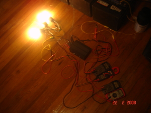
Bad connections I know but the tests were made with #8 wire for the input.


As I said before in my writeup Here, using too much inductance would cause low output currents. The tests (chart number 1) show that this is true but it also illustrates that using too much inductance hurts the converter's transient response. The output voltage started at 115.60V and as load was added to the output, voltage continued to drop. With only 3 60W 120Vlight bulbs the voltage was down by 17.2V.


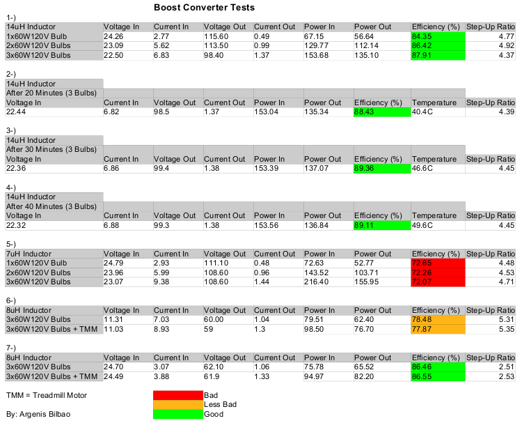
Click on the picture to get the PDF version.


The good thing about having bigger inductance is that efficiency remained very high even though the Step-Up ratio was relatively high. It might work well in situations that the load will be constant.


Looking at the results I decided to cut the inductance in half. With half the inductance the efficiency for the same test dropped enormously as seen in chart number 5. On the other hand the transient response was great. The efficiency drop was an expected situation because the step up ratio is very large and the input voltage was relatively low. Better efficiency can be achieved by using 48V and the same Step-Up ratio for example.


Then I decided to use 12V nominal input and 60V output for then next test. With this one the Step-Up ratio was the greatest but the efficiency was higher than in the previous test because I increased the inductance to 8uH. This value seems to give the best transient response and efficiency.


The same test was repeated at 24V nominal input and as expected the efficiency rocketed. Looks like 90% of the job at building this type power power supply is to find the right core material and inductance for the desired operating range. After all the tests it is obvious that running the boost converter in normal conditions eg (12V to 24V, 24V to 48V) would yield efficiencies over 95% easily.


More tests will come later.

« Last Edit: February 24, 2008, 04:26:52 PM by (unknown) »

joestue

  • Hero Member
  • *****
  • Posts: 1764
  • Country: 00
Re: Boost Converter Tests
« Reply #1 on: February 27, 2008, 05:07:51 PM »
Can you estimate magnetic losses? and separate these from switching losses and reverse recovery losses?

I'm thinking a lower frequency would be more efficient, but that also depends on many other factors.
« Last Edit: February 27, 2008, 05:07:51 PM by joestue »
My wife says I'm not just a different colored rubik's cube, i am a rubik's knot in a cage.

s4w2099

  • Full Member
  • ***
  • Posts: 234
Re: Boost Converter Tests
« Reply #2 on: February 27, 2008, 07:01:32 PM »
I am not too sure but I believe that core losses are given in the ferrite core's datasheet. They provide a graph with losses based on material type, temperature and other factors that I am yet to study. I used P material cores.


Yes lowering the frequency would yield better efficiency but I would not be able to use the boxes that I have because the coil would be too big. Anyways I think that the efficiency was very good for the delta voltage I was doing the tests on.


When I find some more time I will do some tests with much more conservative delta voltages like the ones typically used in RE like 12V to 24V and 24V to 48V.


« Last Edit: February 27, 2008, 07:01:32 PM by s4w2099 »

joestue

  • Hero Member
  • *****
  • Posts: 1764
  • Country: 00
Re: Boost Converter Tests
« Reply #3 on: February 27, 2008, 07:48:50 PM »
Core loss is something you can estimate from the data sheet.

But unless you want to do a FEA and use a spectrum analyzer to determine harmonic loss, which can be more than 50% of total core loss because the manufacturer uses a sine wave to get those marvelously low numbers on their data sheets.


Well naturally component cost rises with the square of the efficiency.

lol.


Anyway great work, I with I was back in a position where I could build my own electronics.

« Last Edit: February 27, 2008, 07:48:50 PM by joestue »
My wife says I'm not just a different colored rubik's cube, i am a rubik's knot in a cage.