I've been looking at buck controllers to charge batteries. It finally downed on me on the weekend that batteries can self regulate when needing a charge, and I don't need to regulate voltage when batteries need charging. I need to regulate current going into batteries.
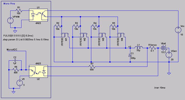
My first attempt at building a PWM switch could generate nasty volts/amps dips and spikes, so I'm trying to merge a micro controlled PWM signal with a SMPS buck/boost controller topology. It's not an optimized circuit, but this is what I have now:

The LTSpice Model.
Microcontroller signals are on the left. The micro is optically isolated from the power circuit. VPWM is the signal from a micro PWM pin. M1 to M4 are 4 parallel MOSFETs. Vcc on the right is MOSFET power. VGen is wind will voltage and Vbat is battery voltage.
A regular Buck/Boost topology would need a diode. Anywhere I put a diode to regulate back EMF from the coil has little effect.