Author Topic: PWM Switch # 3  (Read 4112 times)

0 Members and 1 Guest are viewing this topic.

bigkahoonaa

  • Jr. Member
  • **
  • Posts: 57
PWM Switch # 3
« on: February 26, 2008, 07:26:14 AM »
I've been looking at buck controllers to charge batteries.  It finally downed on me on the weekend that batteries can self regulate when needing a charge, and I don't need to regulate voltage when batteries need charging.  I need to regulate current going into batteries.


My first attempt at building a PWM switch could generate nasty volts/amps dips and spikes, so I'm trying to merge a micro controlled PWM signal with a SMPS buck/boost controller topology.  It's not an optimized circuit, but this is what I have now:
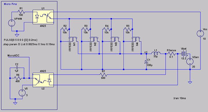


The LTSpice Model.  


Microcontroller signals are on the left.  The micro is optically isolated from the power circuit.  VPWM is the signal from a micro PWM pin.  M1 to M4 are 4 parallel MOSFETs.  Vcc on the right is MOSFET power. VGen is wind will voltage and Vbat is battery voltage.


A regular Buck/Boost topology would need a diode.  Anywhere I put a diode to regulate back EMF from the coil has little effect.

« Last Edit: February 26, 2008, 07:26:14 AM by (unknown) »

Flux

  • Super Hero Member Plus
  • *******
  • Posts: 6275
Re: PWM Switch # 3
« Reply #1 on: February 26, 2008, 01:07:49 AM »
You are slowly getting there this was the first dawning of reality.


Flux

« Last Edit: February 26, 2008, 01:07:49 AM by Flux »

BigBreaker

  • Sr. Member
  • ****
  • Posts: 302
Re: PWM Switch # 3
« Reply #2 on: February 26, 2008, 08:33:02 AM »
Yes, looking quite good.


Just a thought... what if you put a pick up coil* around your power inductor to sense current for the micro? or used a Hall effect current sensor?  Both solutions provide isolation and may be a better analog solution.


I'm a bit concerned about using an optoisolator to convey an analog signal to the micro's A/D.  I guess I'm used to seeing them used for digital signals.  Perhaps Flux or Amanda has experience here.  My two cents would be to avoid trusting the opto's transfer function in the analog domain.


In later revisions I'd also expect to see a volt input from the high side of the battery bank and an RPM sensor from the rotor going into the micro.  It would be nice to have some beefy relays in place to short the turbine out if the MOSFETs cascade fail or some other shutdown event occurs.


*You could connect two coils to your micro if you have the extra analog input.  The coils would have different turn counts so that low current and high current conditions are well covered within the voltage range of the micro's A/D.  Diodes can protect against over voltages/currents.

« Last Edit: February 26, 2008, 08:33:02 AM by BigBreaker »

bigkahoonaa

  • Jr. Member
  • **
  • Posts: 57
Re: PWM Switch # 3
« Reply #3 on: February 26, 2008, 09:20:24 AM »
Yes, I'm a bit slow at this stuff.  I's only taken me about a year.
« Last Edit: February 26, 2008, 09:20:24 AM by bigkahoonaa »

bigkahoonaa

  • Jr. Member
  • **
  • Posts: 57
Re: PWM Switch # 3
« Reply #4 on: February 26, 2008, 09:43:34 AM »
Trying to get an opto like the 4N25/35 to operate linearly to sense an analogue signal can be a bit tricky.  The resistors on either side need to be adjusted.  I like the ideal of a Hall Effect sensor, but I've never used one.


I don't have it in this diagram, but the micro also has control over a bank of relays that can be used to divert current to dump loads or short wind mill coils.  I also have two RPM sensors.  One uses an LED and LDR to sense each revolution, but this one can only go down to about 90 RPM because of limitations on the micro operating at 4MHz.  The other senses frequency coming from the wind mill and converts it to RPM.


« Last Edit: February 26, 2008, 09:43:34 AM by bigkahoonaa »

Flux

  • Super Hero Member Plus
  • *******
  • Posts: 6275
Re: PWM Switch # 3
« Reply #5 on: February 26, 2008, 10:06:43 AM »
Opto isolators can manage volts well enough but they are little use operating from shunts unless you use tricks to fool the voltage threshold.


Hall current sensors are excellent but a bit costly and greedy on power. They are probably justified to save all the hassle of using opto isolators with op amps and opto feedback.


Flux

« Last Edit: February 26, 2008, 10:06:43 AM by Flux »

mtbandy

  • Jr. Member
  • **
  • Posts: 53
Re: PWM Switch # 3
« Reply #6 on: February 26, 2008, 11:24:46 AM »
The usual way to measure current like this is to convert the small voltage across a known shunt resistance into a fixed frequency / variable duty ratio signal (so duty ratio becomes proportional to current) and pass this through an opto to the logic side of the circuit, so it swings from 0v to your ADC reference voltage (usually 5v). A simple low-pass filter on this signal results once again in an analogue level that you feed into your ADC. Have a look at the IR2175, it's a very nice current sense IC that does just this.
« Last Edit: February 26, 2008, 11:24:46 AM by mtbandy »

commanda

  • Hero Member
  • *****
  • Posts: 731
Re: PWM Switch # 3
« Reply #7 on: February 26, 2008, 01:29:16 PM »
I need to regulate current going into batteries.


Wish I had a dollar for everytime I've stated this.


The IL300 is a linear optocoupler.


Personally, I make the circuit ground be the end of the shunt, and use an op-amp to amplify the shunt voltage, and forget the opto.


http://www.fieldlines.com/story/2004/9/4/193922/2839


Amanda

« Last Edit: February 26, 2008, 01:29:16 PM by commanda »

domwild

  • Sr. Member
  • ****
  • Posts: 357
Re: PWM Switch # 3
« Reply #8 on: February 26, 2008, 08:04:49 PM »
Big,


Thanks for that. Interesting circuit. Like the idea of software rather than hardware changing the duty cycle of the PWM. Even I understand how a Picaxe can be made to change the PWM parameters.

« Last Edit: February 26, 2008, 08:04:49 PM by domwild »

BigBreaker

  • Sr. Member
  • ****
  • Posts: 302
Re: PWM Switch # 3
« Reply #9 on: February 27, 2008, 08:15:58 AM »
Flux is right - the opto won't work as shown in the schematic.  The shunt will not provide the voltage drop for the opto's LED.


The pick up coil solution is complicated by the fact that it misses the constant current portion of the signal, like a transformer would.  If the current reliably dropped to zero at some point in the buck cycle, you could use that to rezero the sensor, but that isn't generally the case for bucks.


A Hall sensor or "going naked" might be your best bet.

« Last Edit: February 27, 2008, 08:15:58 AM by BigBreaker »