DIY Panel:
I've had this little box with 19x one watt solar cells on the shelf for about 10 years; decided that it was about time to make a panel. Googled the board and web; thank you to everyone that's posted their projects!
With only 19 cells, I thought about making a 6 volt panel and a booster circuit but figured that a 12 volt panel would be much more useful. I didn't find anything on cutting solar cells in half so I had to wing it... I used a small carbide tool from my mini-lathe to score the cells and then snapped them. I broke the first three into pieces but managed to get the remaining fifteen snapped more or less in half. I pieced together the broken ones and tested all the cells to make sure that there wasn't a weak cell that would hold the panel back. I ended up with 36 pieces that I figured were good enough. You can see some of my patchwork in this picture:
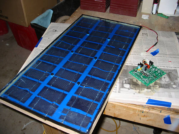
(blue film is still on the outside of the cover.)
I didn't have any solar panel tape but I did have some flat Monster Cable. I cut it in half lengthwise so that it wasn't too wide and soldered the cells together in groups of six.
The panel backing is made of 5/8" thick multi-ply plywood. I primed and painted it, then used a drill to make islands of bare wood where the center of the cells would be. Later, I put a dollop of silicone at each site to hold a cell in place. (Silicone glue sticks to bare wood much better than finished wood.)
I laid out the cells upside down and finished soldering. I used a bunch of nuts to set the spacing then put the backing, upside down, on top of the cells.
I waited about four hours then turned the panel up. Sunny! So I took it out an measured about 21 volts open and 1.2 amps shorted.
The next day, I put the sides and top on. The sides are 1/4" multi-ply and the top is 3/32 polycarbonate. I put some supports in the middle to help keep the cover away from the cells. Glue of one sort or another holds it all together.
Final dimensions are 14" x 27" x 1". and I estimate that it weights six or seven pounds.
MPPT-ish booster for 24v use, work in progress:
Winter and Spring there's more wind so I wire my mill for 24 volts. I decided that I'd like to make a booster after all so that I can add my meager mix of 12 volt panels into the mix.
Turns out that an old rev of a motion control board I made has a DC-DC converter on it and I have a bunch of them left. With a couple of trace cuts and a few jumpers, I leave out the booster controller chip (MAX643) and wire the FET to a PWM port on the microprocessor. (An Atmel ATMega168.) You can see the work in progress on the right side of the panel. The empty socket is for the 28 pin microprocessor. Most of the empty board is for motion control and not needed but the board does support both RS232 and a ZigBee transceiver so, if it works out, it'll be easy to integrate it into the data acquisition system.
Naturally, I want MPPT ... I saw an image of voltage versus current at different levels of sunlight; the MPPT line was practically straight. In this image the maximum power point looks like about 84% of the open circuit voltage. I searched some commercial panels and those that gave a spec typically had MPP at 75% to 80% of max voltage.
So I figure, forget measuring current and calculating power, just look at the open circuit voltage and then load to a calculated MPP voltage. I googled some more and found references to this approach in some IEEE papers but am not a member and can't read the pages. Still, it seems like it'll work so I'll give it a try. I'm thinking to turn of the booster for a bit, measure the voltage, then load up the cell until I get to 80% of that voltage. That might not be exactly the MPP, but I think it'll be good enough that it won't matter.
But I have two questions before I finish building the booster...
Questions:
One -
How long to I have to keep the booster off before I can measure the open circuit voltage of the panel? I've seen pages on RC circuit timing but I don't know what the "R" is. I realize that there's some resistance in the input filter capacitor and that the panel has some resistance-equivalent as well but I don't have a clue what those would be. Naturally, I want the booster-off time to be as short as possible so that I waste the smallest amount of energy.
I would be nice if it were a few microseconds, then if I sample every two or three seconds, the energy waste will be negligible.
Two -
I'm a bit confused about how to shunt the panel when the batteries are full. (Not that I'm worried about the 20 watts overcharging my 400 amp-hour bank, it's more for "completeness" that I'm curious.) I assume I'll have a FET to ground on the input; how much heat does it dissipate?
One thought train tells me that if it's a 20 watt panel then, that has to go somewhere, so it's 20 watts in heat in the FET.
Or: if the FET, for example, has an Rdson of .030 ohms, then watts = I-squared times R, or 1.2 amps (short circuit current of the panel) x 1.2 amps x .03 ohms = .04 watts. Or if the board can support up to four amps then 4 x 4 x .03 = .5 watts.
Or: Maybe maybe I need a current limiting resistor in there with the FET...
Or: something else that I don't understand [yet!]
If you can help, I'd really appreciate it!
Thank you very much,
- Ed.
