Author Topic: Murdered in the name of Science  (Read 4989 times)

0 Members and 1 Guest are viewing this topic.

s4w2099

  • Full Member
  • ***
  • Posts: 234
Murdered in the name of Science
« on: October 20, 2008, 02:09:36 AM »
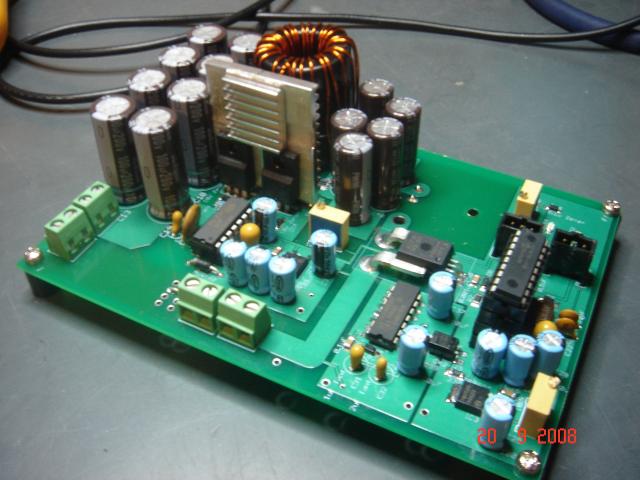
I just wanted to let you all know how my MPPT controller was coming along. I posted pictures of it some time ago bu I still had not posted any test data. Here is a picture for refreshing out minds:


First I want to talk about the topology that I am using. I am using for this project a synchronous buck converter with a diode on the output like shown below.


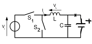
The reason why I put a diode on the output was to help me during the development of the program that the micro controller will be running. If the diode is not in place there is a big possibility that under certain conditions like absence of input or duty cycle being too low the converter will then dissipate energy thought the low side MOSFET. This happens because MOSFETs conduct electricity both ways so if there is no input voltage the current from the batteries will flow backwards and over current the MOSFET if the duty cycle is too low.


On the final product this diode will not be there it is just there for now until the program is 100% bug free.


Recently I got a set for harbor freight like amorphous solar panels 3x15W panels. They are connected in series (36V nominal) and are located on my roof. I dont know what angle the roof is at, but this is a pretty standard house. Anyways... the power is transfered down thought roughly 50' (one way) 12AWG wire into a small knife switch and then into my MPPT controller.


Then the controller goes to an automotive 10A fuse and into two 6V 220Ah batteries in series (12V nominal) which I previously discharged to about 5V with a fan. (Thats the murder right there)


After letting the batteries charge for a bit their voltage went up to ~10.5V (10V is the min battery voltage for my controller to work). I recorded an efficiency of 86% with an output current of 2.1A into the 12V battery bank voltage quickly went from about 10.5V to 12.40V. I was expecting it to remain in the 10-11 volt range as it was supposed to be FAIRLY discharged. I thought 26W was very low power coming from a 45W solar panel array so I decided to reprogram the PIC and use a potentiometer to manually adjust the duty cycle and see the MPP myself.


Again I was disappointed with the output 26W so the algorithm was not the problem. Then I monitored the input power with amp+voltmeter. I found that the panels were just not delivering anywhere near the rated output. I have heard before that amorphous panels do not give the rated output until they are broken in dont know if that is true or not. If anyone has any info on it I will be very happy to get some feedback on this issue.


I tested the short circuit current to be almost 1A in full sun. The input voltage to my converter at MPP was 50V. The ambient temperature was ~25C, I have no clue about panel's actual temperature. Maybe the inclination of the roof is not optimal?


I know for certain there is no problem with my controller because I got the same results by handling it by hand as with the automatic algorithm and the efficiency is not bad at all for this little power range. That efficiency would have been much better if the array would deliver more power.


So please anyone with info on these panels let me know what you usually get into a 12V battery


I have not been able to do many tests on it because Ive been very busy lately but next time I will load the battery down to keep the voltage from going up to see how the current increases when the voltage decreases. Ill keep posting hopefully tomorrow.

« Last Edit: October 20, 2008, 02:09:36 AM by (unknown) »

dnix71

  • SuperHero Member
  • ******
  • Posts: 2513
Re: Murdered in the name of Science
« Reply #1 on: October 19, 2008, 08:24:11 PM »
Those panels put out more than their rated wattage when cool. I put a volt/ohm meter on one panel in full July sun and watched it. I got 18 watts at the start, but it dropped off to about 12 watts in a few minutes as the panel warmed up.


If you string them in series (they are not intended to be set up that way) then you will have internal resistance losses to deal with plus losses from a long run of wire (50 feet) and resistance across the knife switch.


Those are not the best panels to stack in series like that. I partly disassembled one and could not tell for sure if there was a diode included. If they have a diode, then you will have diode losses across the last two in series, as well.

« Last Edit: October 19, 2008, 08:24:11 PM by dnix71 »

tecker

  • SuperHero Member
  • ******
  • Posts: 2183
Re: Murdered in the name of Science
« Reply #2 on: October 20, 2008, 06:46:41 AM »
 You can see from ohms law calc alone you  limiting your power with a series connection especially if you block at each panel . Boosting   panels parallel across your batteries works well .Set up the coil timing with the batteries out and the largest back emf spike scoped at the Drain of s2 and s1 out of the circuit (Blocking at the panels)_.You may have to take the cap out to really get the spikes visible on scope with a small torus  ( I like a larger torus ) . With S1 out panel voltage is sinked through the coil and commutator diode plus back emf to cap and battery in  the off cycle .The  on cycle is where you have   to limit current to give your panels the most potential retained in circuit to give a good push at off cycle   . Setting up the coil with the highest back emf spike gives max use of the coil with the least amount of current used per cycle.

.  
« Last Edit: October 20, 2008, 06:46:41 AM by tecker »

Airstream

  • Full Member
  • ***
  • Posts: 245
Re: Murdered in the name of Science
« Reply #3 on: October 20, 2008, 07:28:49 AM »
The above mono-block paragraph does not work for me. No single statement alone seems to ring a bell, if there is a general trend it is escaping me...
« Last Edit: October 20, 2008, 07:28:49 AM by Airstream »

tecker

  • SuperHero Member
  • ******
  • Posts: 2183
Re: Murdered in the name of Science
« Reply #4 on: October 20, 2008, 08:10:35 AM »
 s4w2099 has a low current problem with the buck circuit and the series panel configuration . I think he can reconnect in parallel and set up a boost circuit to get all the panel power plus the added power from the coil. The batteries and Cap can rise to 15 plus volts and he can hold it there with a frequency adjustment on the timming circuits . I was trying to give a way to coarse adjust the coil with his panel input .
« Last Edit: October 20, 2008, 08:10:35 AM by tecker »

s4w2099

  • Full Member
  • ***
  • Posts: 234
Re: Murdered in the name of Science
« Reply #5 on: October 20, 2008, 09:07:47 AM »
Tecker, I am having NO problems with the converter whatsoever. Converter is working fine with great recorded efficiency even for this low power and the presence of that output diode.


The point of MPPT is to have higher voltage going down the line to loose very little in wiring from low currents and seek peak panel power.


"I think he can reconnect in parallel and set up a boost circuit to get all the panel power plus the added power from the coil." - Are you suggesting coil in boost converter will create energy?


The thing I was questioning was the panel's ratings. Even straight to batteries they are under performing. They make about 6-7Watts straight into batteries while going though controller they make about 10W per panel into controller and about 8.6W into batteries. They are rated 15W though, where are the remaining 5?


They are just behaving like 10W panels thats all.


I have found while googling for this problem the following link where the poster complains about the same issue with these panels and his results seem to be consistent with mine.


http://groups.google.ca/group/alt.solar.photovoltaic/browse_thread/thread/34864c1fb2044a24


I will give them another chance and try when temperatures get cooler, maybe my panels are too hot up there in the roof. I have some good panels but they are mismatched and thats why I got these HF to test with matched panels. I guess I will give it a go with the mismatched panels.

« Last Edit: October 20, 2008, 09:07:47 AM by s4w2099 »

s4w2099

  • Full Member
  • ***
  • Posts: 234
Re: Murdered in the name of Science
« Reply #6 on: October 20, 2008, 09:10:41 AM »
The possibility of loosing any significant amount of power transferring 45W of power@~50V through a 12AWG wire run of 100' (round trip) is very minimal. ~0.9Amps
« Last Edit: October 20, 2008, 09:10:41 AM by s4w2099 »

tecker

  • SuperHero Member
  • ******
  • Posts: 2183
Re: Murdered in the name of Science
« Reply #7 on: October 20, 2008, 09:18:21 AM »
I got ya . Get your money back there's no Quality control sticker I bet. I ran through 18 to get seven from Northern .
« Last Edit: October 20, 2008, 09:18:21 AM by tecker »

ghurd

  • Super Hero Member Plus
  • *******
  • Posts: 8059
Re: Murdered in the name of Science
« Reply #8 on: October 20, 2008, 09:37:33 AM »
"new" HF type PVs make More than their rating for a while.  6 week to 3 months maybe.

But the rated power is under 100% perfect condtions.  Haze, high humidity, improper angle, time of day, etc, make the output lower.


The rating should be thought of as 1A max under perfect conditions, instead of 15W average.

The 1A Isc sounds fine to me for what they are.

G-

« Last Edit: October 20, 2008, 09:37:33 AM by ghurd »
www.ghurd.info<<<-----Information on my Controller

tecker

  • SuperHero Member
  • ******
  • Posts: 2183
Re: Murdered in the name of Science
« Reply #9 on: October 20, 2008, 12:10:16 PM »
 I just want to point out here that the serial connection impeadace is going to gobble up some power there .Two panels are pushing thru and the third is  slightly over loaded and . Meter  the junctions  and look at it  especially when they heat up.
« Last Edit: October 20, 2008, 12:10:16 PM by tecker »

RandomJoe

  • Full Member
  • ***
  • Posts: 120
    • Joe's Time-Waster
Re: Murdered in the name of Science
« Reply #10 on: October 31, 2008, 04:10:44 PM »
The best I ever saw from my HF set of panels was 30W, and that was the first day I unpacked them, with me very carefully adjusting them to get the noonday summertime (virtually straight overhead) sun.


Since then, they have fairly dependably given me 20-25W on sunny days, but that's it.


Be interesting to see if I get any more from them as it gets cooler.  Perhaps the lower winter sun will help since they are now on the roof, which is fairly steeply pitched.

« Last Edit: October 31, 2008, 04:10:44 PM by RandomJoe »

s4w2099

  • Full Member
  • ***
  • Posts: 234
Re: Murdered in the name of Science
« Reply #11 on: October 31, 2008, 09:06:57 PM »
I have been taking a lot of exams lately so I was unable to play with the panels as much as I would want. I am done now though.


Last week I was able to do a minor test. I climbed up my roof with the garden hose for a while. The sun was straight up. I came down to see the amp meter and it was measuring 200mA more than before. That tells me they are getting to an uncomfortable temperature.


I guess I will leave more space between the roof and the panels and see how they behave like that. Also I noticed that the inclination angle of my roof was not great for this season, Ill try to fix that hopefully tomorrow.


After watering the panels I got 30W into the batteries so that means that assuming the same efficiency of 86% panels would have been making almost 35W. I suspect efficiency would have had increased at that time but I didn't really checked.


Here is a picture of it working at 91% efficiency:


From the left: input voltage, input current, output voltage, output current


The output current is measured from a homemade shunt that drops 10mV per Amp thus the meter reads 19.6mV (1.96A). I have to get rid of that crappy knife switch just because it sucks but I am not having any significant voltage drop across it because of low input current.

« Last Edit: October 31, 2008, 09:06:57 PM by s4w2099 »