Author Topic: PMA rpm test.  (Read 3650 times)

0 Members and 2 Guests are viewing this topic.

Jerry

  • Hero Member
  • *****
  • Posts: 1519
PMA rpm test.
« on: December 09, 2008, 04:55:12 AM »
I've been testing the Hornet GM alternator stock and 2 diferant mods.


Since I had the bench setup for testing rpm and output on the GM alts I decided to check the rpm #s on my 403 as well.


Fisrt is the Hornet GM alt with there single NEO ring magnet replacing the original rotor coil. The first test is with all 3 phases seperated, a fullwave bridge rectifier for each phase, a 160,000 uf cap on each bridge dc termanals, then these 3 seperate dc outputs wire in sires.


Next is the same setup but NO caps.


Next is the GM alt stock with the original GM 3 phase diode/bridge. I'll use JR for "Jerry Rigged"


 GM ALT JR+3 CAPs     GM ALT JR no CAPs        GM ALT Stock star/Hornet

 1 amp 556 rpm        1 amp 742 rpm             1 amp 1124 rpm


 2 amp 594 rpm        2 amp 774 rpm             2 amp 1153 rpm


 5 amp 693 rpm        5 amp 873 rpm             5 amp 1227 rpm


7.5 amp 785 rpm      7.5 amp 925 rpm           7.5 amp 1284 rpm


Here are the #s for the 403. This 403 is 48 volt, so it was dificult to make an exact compairison to the above 12 volt machines. It however gives a good idea of the requiered rpm for an SW-403. The .25 amp # for the 403 is equal to the 1 amp figure of the 12 volt machines as far as wattage is concerned. You can see it has a much higher rpm requierment for cutin.


I based cutin for the 12 volt machines at 12.7 volts and therefor 50.8 volts for the 403.


                     403 test #s


         .25 amp   860 rpm   12.56 watts  cutin rpm


         .5 amp    922 rpm   25.80 watts


         1.0 amp   997 rpm   50.71 watts


         2.0 amp  1111 rpm  102.80 watts


         3.0 amp  1223 rpm  156.36 watts


         3.8 amp  1325 rpm  201.47 watts  prime drive max rpm.


The wind tunnel test will be the fun part. I'm looking forward to compairing the "Jerry Rigged" plus caps, with "Jerry Blades" to the stock Hornet and the SW-403 in the wind tunnel.


                        JK TAS Jerry


« Last Edit: December 09, 2008, 04:55:12 AM by (unknown) »

ghurd

  • Super Hero Member Plus
  • *******
  • Posts: 8059
Re: PMA rpm test.
« Reply #1 on: December 09, 2008, 01:05:54 AM »
Hey Jerry,

Great timing.


I have been talking with someone about this on a 2 phase Garbogen.  He has a nice existing assembly to test the idea a little more.  His available caps are a bit under sized.

I think the caps will help more in a 2-ph or single phase machine.


Also, the worse the line voltage loss the more the caps will help.

I figure you did not have much line loss in a bench test?


When willib and I spoke of it years ago for stepper motors and tiny dual rotor PMAs charging AAs, nobody cared.


Maybe this time it will get some attention.


G-

« Last Edit: December 09, 2008, 01:05:54 AM by ghurd »
www.ghurd.info<<<-----Information on my Controller

Jerry

  • Hero Member
  • *****
  • Posts: 1519
Re: PMA rpm test.
« Reply #2 on: December 11, 2008, 09:35:26 PM »
Hi G.


The Garbogen is not a good canidate for caps. It has run and start windings. These have diferant potential.


The runs are wound with fewer turns of heavyer wire, the starts have more turns of smaller wire.


It was a single phase motor that become a 2 phase pma. Each phase has its own and seperate fullwave bridge rectifier then there dc outputs are perelelled.


Apling a cap at this point has no effect.


If the starts and the runs were identical and the 2 bridge dc ouput were wired sires, then the caps would have the desiered effect.


However this would make for some very high voltage.


I've been expirimenting with GM car alternators. These are used by Hornet, Malard, Freetricity and such COs.


I have a Hornet and it sucks. 2 problems with these types of machines.


  1. they are car alternators and nned very high rpm.
  2. there very high rpm blades don't work till 15 mph.


My attemp is to make the alternator work at much lower rpm without rewinding it with 22 ga. wire and use the stock windings. Then use a blade that actuly responds to low wind.


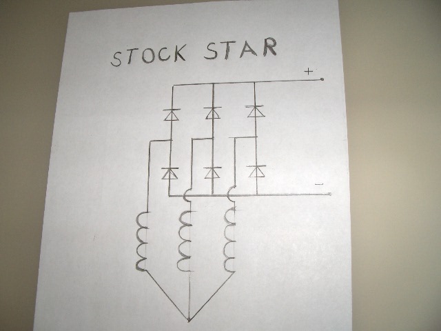
These alts are 3 phase. In the star mode a phase is making 10 volts and its in sires with the next phase the voltage is not 20 its 17v.


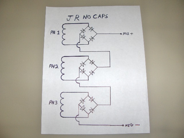
My scheam treats each phase as a seperate power supply. Coil to bridge to cap.


This makes a nice stable power supply. Now when I sires these 3 power supplies the volage is much higher and or the rpm requierment is greatly reduced.


On a typical ac power supply, when a power transformer is supplying 10 volt ac at the AC terminals on a fullwave bridge rectifier and there is a cap conected to the DC termanals of the fullwave bridge rectifier the DC voltage on the measures around 14 v.


3 X 14v = 42  is a better result then 2 X 10v = 17 volts.


Each phase of a car alternator must be capable of handeling the alternators rate amperage.


I'm working with 60 amp alternator here. I'm not sufering any capability of amperage here but the voltage is greatly increased or the rpm is greatly reduced.


Even with these improvments this is still a high rpm small blade machine. But now Its a more usable worthless machine.


A 3 phase moror conversion might be a good canidate for this mod if you are needing 500 volts for a WindyBoy grid tie inverter?


But not the Garbogen. It noes not fit this scheam.


Here are the schimatics of the GM alt mods I,ve made.


This is the stock GM alt 3 phase. It is the worst prefomer in this test.


Here is the "Jerry Rigged" version without the caps it did better then star by far but not as good as the caps version.


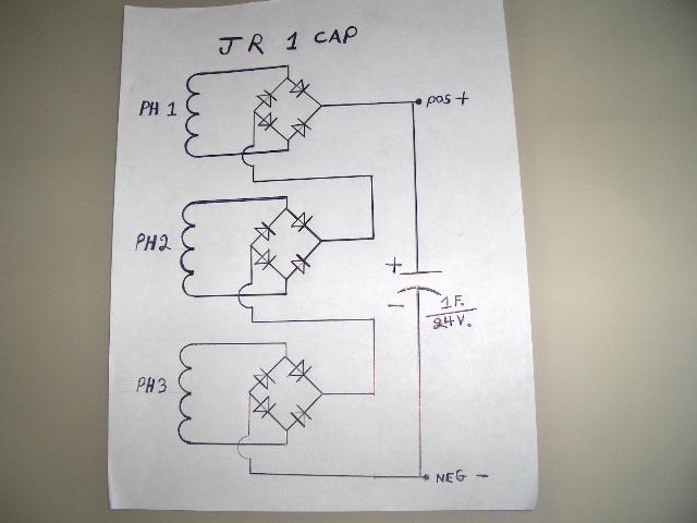
Here is the version with one single 1 farrad cap accross the 2 outside terminals. It did not work any better then the no cap version.


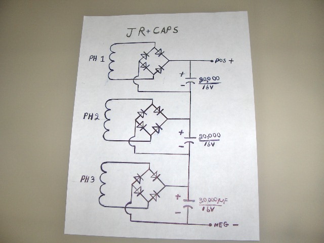
Here is the best preforming mod. a cap on each bridge DC output. 3 DC power supplies wired in sires. I did this with some 20,000 UF- 16 volt caps and some 630,000 UF- 6.3 volt caps. The preformance was the same.


                       JK TAS JERRY

« Last Edit: December 11, 2008, 09:35:26 PM by Jerry »

Jerry

  • Hero Member
  • *****
  • Posts: 1519
Re: PMA rpm test.
« Reply #3 on: December 11, 2008, 09:44:04 PM »
Whoops same picture twice?


                     JK TAS Jerry

« Last Edit: December 11, 2008, 09:44:04 PM by Jerry »

oztules

  • Hero Member
  • *****
  • Posts: 1477
  • Country: aq
  • Village idiot
Re: PMA rpm test.
« Reply #4 on: December 12, 2008, 09:36:14 AM »
Hi Jerry,

If you get a chance, perhaps you could put a few hundred uf directly across the coils before the rectifier as a separate addition to  the series caps across the jerry rig (last photo.


With the F&P units, they found this lowers the rpm. Too much and it kills it. too little and it does not work too well. Their pole count is very high..... but it might be worth a try as you have the setup in place to test his out... it may help?


.........oztules

« Last Edit: December 12, 2008, 09:36:14 AM by oztules »
Flinders Island Australia

Jerry

  • Hero Member
  • *****
  • Posts: 1519
Re: PMA rpm test.
« Reply #5 on: December 12, 2008, 10:44:27 AM »
Hi oztules.


Do you have a sugjestion on a starting point in UF. I know it will be non  polerized.


Motor run cap I'd think. I have a large collection of these caps from 3 UF to 80 UF.


Thanks for the idea. What kind of improvement do you see on the F&P. I have a F&P also (thanks Tom W ).


                           JK TAS Jerry

« Last Edit: December 12, 2008, 10:44:27 AM by Jerry »

oztules

  • Hero Member
  • *****
  • Posts: 1477
  • Country: aq
  • Village idiot
Re: PMA rpm test.
« Reply #6 on: December 12, 2008, 12:04:32 PM »
Jerry,

here is a link to work done by Gordon.

:


http://www.thebackshed.com/Windmill/FORUM1/forum_posts.asp?TID=1138&PN=1&TPN=1


He used 200uf in the first experiment. @350 rpm, current into the battery increased from 3A to 11A. This is not a fix all by any means.


It seems to carry with it it's own problems..... but used judiciously, it may offer a way to lower the rpm characteristics of the alt. If too much uf is used for the pole count, it will cripple the upper rpm range, but may provide a useful way to change the dynamics a bit.


non-polarised caps made from back to back dc electro's were used in this configuration successfully.


Anyway, have a read, it it an interesting discussion.


..........oztules

« Last Edit: December 12, 2008, 12:04:32 PM by oztules »
Flinders Island Australia