New MPPT algorithm.
I will talk a little bit about the software features now. Well, there is not much to say about the three stage battery charging other than the fact that it is capable of sensing the amount of current that the battery bank is absorbing during the absorption stage to determine when the batteries are fully charged and switch over to float charge mode. Unfortunately I can only set this current in the software because I ran out of ADC pins in the microcontroller. I set mine to change over to float at about 1Amp.
Second feature is very handy if I ever wanted to use my converter as a simple open loop buck converter with a higher voltage windmill to charge a low voltage battery bank. The input of this converter can take up to 100V. The output can only be used with 12V or 24V battery banks without external hardware (which I am going to speak about later). The duty cycle or output voltage can be adjusted via a potentiometer while working in this mode (output voltage will rise linearly with respect to input voltage). Setting my converter up to work in this mode is very simple, just need to turn it off. install a shorting block in a dedicated jumper for this purpose and turn on the power.
The over current protection is nothing new so I will not go into details about it. I prefer to talk about how I tested this to work. First I connected 4x12V batteries in series to the input of my converter and a single 12V battery to the output and configured it to work in MPPT mode. By this time I didnt had the over current protection enabled in the code, so what I expected happened. The MPPT looked for the maximum power point and the current in the 12V side went up to 50A+ and fuse blew. No components damaged. Then I enabled the over current code and the output current remained under 25A very nicely until the battery reached charged state.
The temperature protection consists of two cooling stages. First of the temperature reaches a set point, then microcontroller switches on a fan to try to keep the temperature under control. The second stage is reached if the fan is unable to keep the temperature at a reasonable value. Then the converter shuts down until the temperature goes below the first temperature set point. After this happens then the converter resumes normal operation automatically.
Now this feature is a weird one. The Disconnect-output-while-on protection feature simply turns the converter off if the output is disconnected from the batteries while the input is still connected to the converter. I did this because if the input voltage is an 48V nominal array the MPPT algorithm keeps tracking and it can make the output high voltage too. This converter takes power from its output so high voltage would rush into the logic circuitry if output is disconnected.
The MPPT algorithm that I used is the standard "Perturb & Observe" method in combination with IV curve calculation. Ill explain: Every 5 minutes the microcontroller sweeps the duty cycle from 0 to 99% (1) to get the minimum duty cycle at which the panels can output current into the batteries and (2) to find the duty cycle at which the array made the most current into the batteries. After the sweep is done the routine sets the converter PWM to the highest output current it found during the sweep. Then the P&O method is used to dynamically find the best operating point between the minimum duty cycle found by the previous sweep and 99%. P&O modifies the duty cycle every 100ms more or less. This is a very nice approach because partial array shading can create multiple local maximum power points and P&O can get confused trying to locate a LOCAL maximum instead of the ABSOLUTE maximum.
Now, other things. I left some pins in that header for a serial port. I will be using the SPI port in slave mode to transmit data from the MPPT to a logger unit I am currently designing. Here is a picture of it:
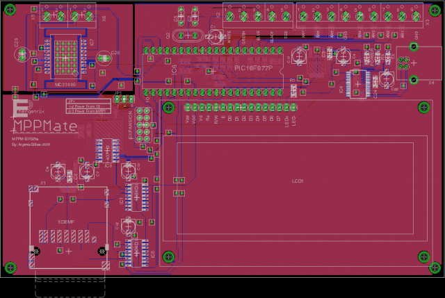
The rest of the pins were left in place in case I wanted to attach an auxiliary power supply to be able to use this baby with a 48V battery bank.
As seen that board is still not ready but from the picture you can see it has an LCD to display data, an SD card slot, a USB connector in case I want to connect a computer to extract the data. Also on the top left there is a Full bridge driver IC in case I make a mechanical solar panel tracker. It can only handle 5A into a DC motor though. This board also has 7 ADC channels to monitor anything else I want to.
It will be fun when I finish that board and mate it with my MPPT board. I just hope it works first try :-)
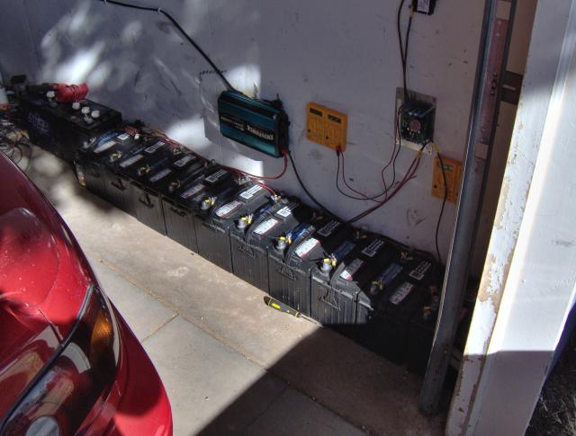
I did an upgrade to my battery bank. I got a few marines from the autoparts store 10x12V@75Ah. I know they are not the best but I have very little consumption and little current is drawn from them. I also got some high voltage solar panels (48V nominal) to feed the new batteries configured for 12V. I dont recommend 12V systems to anyone but as Ive said before it allows me to test at the very worst conditions I could get (low volt out with high volt input). Here is a picture of the bank:
I am very satisfied with the performance of the MPPT converter. It is definitely not cost effective to build such a small unit because 95% of the components needed for this one are also needed for a 150A version. So thats my next goal after I finish the the mppmate board. I will jack the input voltage to 300V or 400V and output current to 100A or 150A. Hopefully will keep good efficiency on the low power side. The only reason why I made it so small was to achieve very high efficiency at low power levels and I hit the jackpot.
