I've been working on this single rotor mill since last summer on and off throughout the school year. Finally it's getting toward time to put up the tower and get everything going (as soon as the snow melts). Basically, I've started trying to get some decent numbers this week on how much power I can produce and what RPM I should be expecting to achieve, etc.
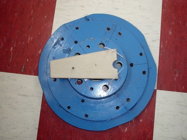
To test the generator I shaped a piece of wood that would mount on the front of my rotor and stuck a couple of screws into it on either side of the center. I am using a T-handled allen wrench in a drill that rests on these screws and spinning it up with the drill. It's a bit crude, but it seems to hold up alright so far.
At first we've been using my small cheap cordless drill (with dying batteries) to test so my results have been lackluster. I've been using the school's physics lab test equipment though which has been nice and provides me with graphs and relatively accurate RPM measurement (with a bit of calculation).
So far the max I've gotten out of the generator has been 39.6 watts. I've got a 3.6 ohm load ( 6 18 ohm resistors in parallel) on it after the rectifier. I don't know what RPM I was turning at that time though (I hadn't hooked up all the equipment yet).
Then I got all the equipment set up and here is what I collected. DC volts: 5.94 DC Amps: 1.5 RPM: 77.5 with the 3.6 ohm load. For a grand total of 8.91 watts... hey my drill battery pretty much had it. Here is the pretty graph that I'm using to calculate the voltage, sadly it only measures up to 10 volts so I'm using a voltage divider to get 1/12 the voltage (eg. the real voltage is the voltage on the graph times 12).
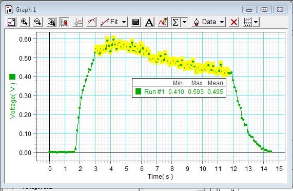
Pretty neat graph, eh?
Tests will be continuing the rest of the week (I finally obtained a corded drill with some real power). I'll be updating with graphs of my progress and output. Once I've mapped the output of the generator I'm going to program a controller that will allow me to heat an element based on how much power I'm making. It is exciting to see the amps climb on the meter as I go.
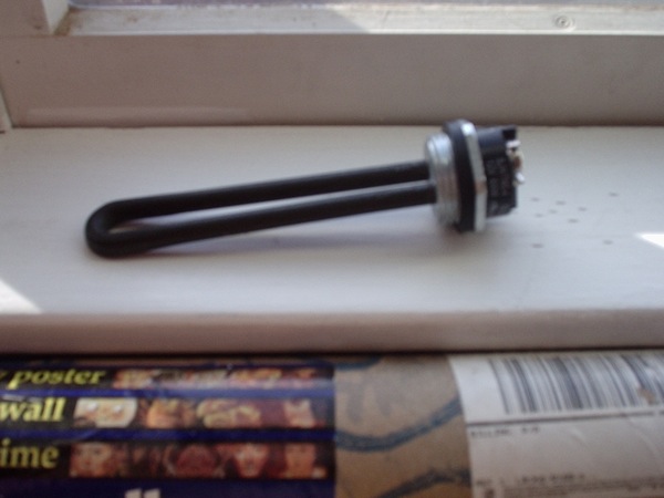
Here is the 12volt heating element I plan on using. I know it's not going to provide all my water heating needs but it's sort of a little experiment and it means I don't need any batteries.