This weekend, I got the control electronics finished off enough to start putting some charge into the batteries from my lone 120 watt solar panel and a 6 amp smart charger.
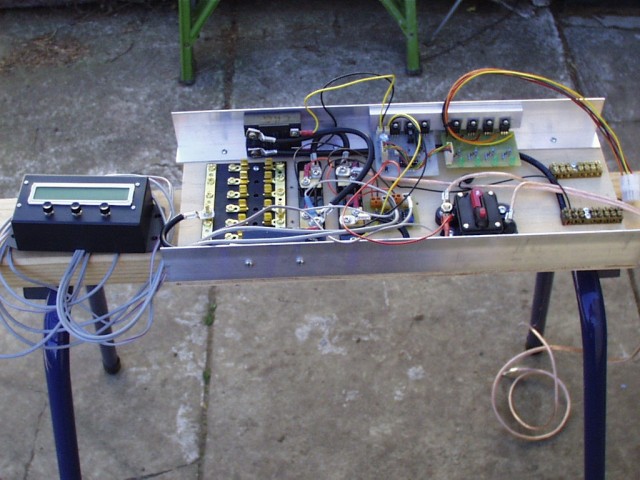
Black box on the left with the lcd and 3 pushbuttons is my amp-hour meter. Was working previously on my SLA batteries, now won't boot. Will investigate later.
Moving to the right is a fuse block for connecting the loads, 2 x current shunts, the tiny little pcb is the amplifiers for the current shunts, a 70 amp circuit breaker, and terminal blocks for the incoming power. On the aluminium angle, one on each side, are a pair of 30 volt, 100 amp, solid state relays. One is the low voltage disconnect, the other is the bulk charge switch.
The 2 pcb's on the aluminium angle is the BMS. Board on the right is the per-cell circuitry, while the board on the left is the control circuitry.
The per-cell cct'y consists of a shunt regulator set at 3.65 volts, and a low-voltage detect set at 2.7 volts. Each of these feeds a common buss, and is opto-isolated. The green led comes on with the shunt regulator.
On the control board, the 3 TO-220 devices are:
one to power the low voltage disconnect SSR,
one to power the bulk charge SSR,
and the one in the middle is a constant current source for the final equalisation charge. The constant current source is in parallel with the bulk charge SSR.
The low voltage signal drives a flip-flop, so once triggered the load stays off until manually reset. The RC network which makes the flip-flop start in reset state needs a bigger capacitor, and silly me forgot a pin header on the pcb for the reset switch.
Pdf's of all the circuitry coming in the next instalment.
Amanda
