After reading a few posts two years ago, I decided to pull some heat from the attic area of my shop. Here's one of the threads:
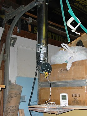
http://www.fieldlines.com/story/2006/1/22/7044/09848And here's a picture of my air duct running up into the "attic" in my shop:

A duct fan (from Home Depot) pulls air from up there down... It's worked nicely. I put a flapper on it to control back draft but that's pretty much it. It's not a lot of heat but over the course of a few hours in can raise the shop temp by 15 degrees or more.
Up to now, the control has been manual. When I've been in the shop, I turn on the fan and see how hot the air is. (The picture shows an indoor-outdoor thermometer with the remote sensor in the duct.) If the attic is warmer than the shop then I leave it on. The only automation I've had was an AC timer; if the weather is nice I could set the timer to run the fan until a little after sunset.
I've only used it for supplemental heat, to reduce the run-time of the furnace when I've been working. I hope to use it this winter as a primary source. This year, instead of "idling" the shop at 55F when I'm not there I'm going to let the temperature drop down to 42F. With the lower set point, there's an opportunity to get more heat from the attic space, particularly when I'm not there and colder is okay. So I built a differential thermostat to automatically turn on the duct fan.
[Here's a description of the thermostat. Because this is specifically for heating, I've posted to in the "heat" section rather than "controls"; hope that's okay...]
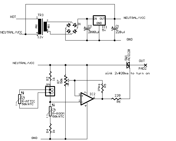
I did find circuits on the Internet. All were basically non-inverting comparators driving a transistor to activate a relay. I had an 2 amp AC switch that I sampled from ST, an ACS120, that I wanted to use and it takes sinking 20ma at at least 2 volts to turn it on so I needed a negatively biased inverting comparator to turn on the switch.
It's time for me to point out that I am not an Electrical Engineer™ but ScottsAI did give me a long lesson in op-amps in a dump controller thread (Thank you!) so I decided to give this one a try without calling for help at the get-go... This is the circuit that I came up. (Parts choices are based on what I had laying around and not really knowing any better.

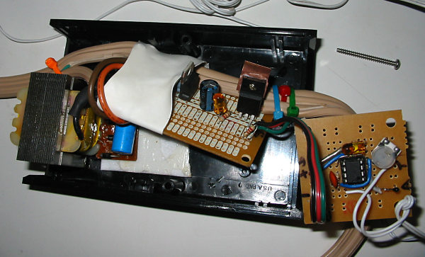
The opamp is a TS921. The power comes from a ripped open wall-wart and the thermistor set came from a dead indoor-outdoor thermometer. I put the regulator and AC switch on one board and the thermostat on another.

I can't say that I completely understand the hysteresis. I get about .1v which at room temperature is about 5F degrees. I think that I offset the zero a bit with the pot so that on-state hysteresis is all on the warm-side and won't keep the fan running when the attic is (just a little bit) colder than the shop. I honestly don't know how linear the thermistor is; that .1 volt may only be part of degree at cold temps... I think that if I were clever that a thermistor in the feedback position could take care of that.
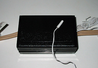
Here's a picture of the box built:

It turns out that, in use, the transformer is warmer than I thought so for now I've had to pull the op-amp board out of the box to get the room sensor away from the heat; real soon now I'll turn the room sensor into a remote so that I can put the op amp board back in.
Okay, I'm not happy that the circuit is not isolated from the mains but I've tried to insulate and isolate as much as I could. I don't feel so bad in there there are neutrals running through every cord in the shop but it bugs me a little to have one running up the air duct in that I don't think someone walking in would expect it to be there... An isolated solid state relay (SSR) might be a better choice than the AC switch if I build this again but for now my budget was zero dollars for this project and I was able to keep to it.
Thanks all,
- Ed.