Author Topic: Buck converter for micro hydro  (Read 8737 times)

0 Members and 1 Guest are viewing this topic.

jeffbirkle

  • Newbie
  • *
  • Posts: 41
Buck converter for micro hydro
« on: January 08, 2009, 05:06:21 AM »
I have a small micro hydro turbine putting out 25 to 70 watts,

depending on water flow (CFM).

The battery bank is 12 volts.

The transmission line is 200 feet.

If I change to a 24 volt battery bank I increase turbine

output from 25 to 32 watts, 22%.

I would like to build and play with a Buck converter to

see if I can increase some more.

I have seen a circuit on this site from "Jaycar electronics"

somewhere,and was wondering about the "switching control

circuit".

Since turbine output is fairly constant, what would I need

for a switching control? A single IC?

Would this work for what I want?


Thanx


Jeff

« Last Edit: January 08, 2009, 05:06:21 AM by (unknown) »

Flux

  • Super Hero Member Plus
  • *******
  • Posts: 6275
Re: Buck converter for micro hydro
« Reply #1 on: January 08, 2009, 01:55:44 AM »
At that power level you only need a simple buck converter but commercially I have no idea what is available. You should be able to build something from the general information on the internet. If you use modest frequencies then layout should not be too critical at that power level.


I don't think you need any clever control scheme for hydro. If the water level is reasonably constant you can probably get away with an open loop control. Just have a pot to manually control the pwm and set it for best results.


Way too expensive and complicated but the smallest mppt solar controller would probably work fine.


Flux

« Last Edit: January 08, 2009, 01:55:44 AM by Flux »

wpowokal

  • Hero Member
  • *****
  • Posts: 1271
  • Country: au
  • Far North Queensland (FNQ) Australia
Re: Buck converter for micro hydro
« Reply #2 on: January 08, 2009, 04:26:57 AM »
Jeff have you checked out Oatley Electronics kits..

http://secure.oatleyelectronics.com//index.php?cPath=81&sort=2a&page=2&osCsid=b945814170
708cf8b328b8ea67230c7e


Or a simple 12-24v off the shelf converter from an auto store, probably as Flux hinted for off the shelf gear a bit pricey, depending on how you view things.


allan down under

« Last Edit: January 08, 2009, 04:26:57 AM by wpowokal »
A gentleman is man who can disagree without being disagreeable.

wpowokal

  • Hero Member
  • *****
  • Posts: 1271
  • Country: au
  • Far North Queensland (FNQ) Australia
Re: Buck converter for micro hydro
« Reply #3 on: January 08, 2009, 04:35:59 AM »
« Last Edit: January 08, 2009, 04:35:59 AM by wpowokal »
A gentleman is man who can disagree without being disagreeable.

tecker

  • SuperHero Member
  • ******
  • Posts: 2183
Re: Buck converter for micro hydro
« Reply #4 on: January 08, 2009, 05:19:58 AM »
 I know this sounds like a slam but your wasting time converting form 12 to 24 volts >If your equipment is happy at 24 volt go with that . To run 12 volt gear make up to basks of 12 .I have no idea what your battery bank is know but it's easily done I assume your ok configuring 12 or 6 volt batteries .
« Last Edit: January 08, 2009, 05:19:58 AM by tecker »

drdongle

  • Hero Member
  • *****
  • Posts: 552
Re: Buck converter for micro hydro
« Reply #5 on: January 08, 2009, 08:21:28 AM »
Just remember that if your battery bank is 12 volts the actual charging voltage needs to be about 13.6-13.8 volts not 12.

You could use a commercial converter like the Astrodyne ( www.astrodyne.com) ASD50-24s15 which is a 50 watt 18-36 volt in and 15 ( 3.3 amps) volts out converter for $71.00 you could than add 2) 5 amp silicon rectifiers in series from the output to drop it to 13.6 volts.


Dr.D

« Last Edit: January 08, 2009, 08:21:28 AM by drdongle »

ghurd

  • Super Hero Member Plus
  • *******
  • Posts: 8059
Re: Buck converter for micro hydro
« Reply #6 on: January 08, 2009, 08:58:27 AM »
If the turbine makes AC, may find some gain with a 2:1 transformer near the batteries.

Would not work for a brushed DC generator (Ametek, etc).

G-
« Last Edit: January 08, 2009, 08:58:27 AM by ghurd »
www.ghurd.info<<<-----Information on my Controller

Opera House

  • Sr. Member
  • ****
  • Posts: 261
Re: Buck converter for micro hydro
« Reply #7 on: January 08, 2009, 10:31:09 AM »
I still can't figure out what you are trying to do.  Are you trying to boost a 12V output generator to 24V OR operate the generator at 24 and convert down to a 12V battery.  Either way, the basic circuit is in one of my postings titled TL494 shunt regulator.  Just need to change the output circuit.
« Last Edit: January 08, 2009, 10:31:09 AM by Opera House »

s4w2099

  • Full Member
  • ***
  • Posts: 234
Re: Buck converter for micro hydro
« Reply #8 on: January 08, 2009, 02:17:00 PM »
I dont quite understand either but if what you are trying to do is to let the generator run at higher speed to get a better match at higher voltage and then convert the voltage down with a regular buck converter then you will certainly be in a world of pain.


You need a buck converter the does not regulate the output voltage or you will stall the machine. So this means that you need one that would let you variate the pulse width and keep it at a fixed value.


This way, your voltage will be lower than the input but it will grow linearly with RPM.

« Last Edit: January 08, 2009, 02:17:00 PM by s4w2099 »

Flux

  • Super Hero Member Plus
  • *******
  • Posts: 6275
Re: Buck converter for micro hydro
« Reply #9 on: January 09, 2009, 01:20:44 AM »
This is hydro and as I see it he has a 12v battery, an alternator capable of higher voltage and a long line. The thing is mismatched and he has seen more power into a 24v battery.


A fixed ratio regulated commercial buck converter may well get him to where he was with the 24v battery but it may be that more than 24v will do even better.  I still think that a simple open loop buck converter without regulation would let him find the best conversion ratio to match the alternator to the turbine and it would help the line loss considerably. I doubt that he will be able to buy such a converter as it would be no practical use for most applications, so back to build one. A solar mppt control would do this perfectly well as it would find the peak point eventually but these are a bit expensive for something working at about 30W.


Transformers may do the job but if it is 3 phase it means 3 of them. Depends what is lying around cheap and the frequency of the alternator. Unless chosen very carefully I suspect the losses introduced would make the end result poor or pointless and to buy transformers new would be costly.


Flux

« Last Edit: January 09, 2009, 01:20:44 AM by Flux »

tecker

  • SuperHero Member
  • ******
  • Posts: 2183
Re: Buck converter for micro hydro
« Reply #10 on: January 09, 2009, 03:48:02 AM »
A buck circuit is fairly simple to make and is ok on efficiency as the shunt goes through the load and the timing is set to  limit current but your not going to see the overall efficiency increase because the 12  volts is a bottle neck . Two 12 volt banks with Transfers is the way to go if you get good numbers with 24 volt charging
« Last Edit: January 09, 2009, 03:48:02 AM by tecker »

Opera House

  • Sr. Member
  • ****
  • Posts: 261
Re: Buck converter for micro hydro
« Reply #11 on: January 09, 2009, 04:52:22 AM »
As in the shunt regulator circuit, regulation is made on the input voltage.  Regulator is basically turned off till the set input voltage (speed) is achieved.  The gain of the regulator can be adjusted to maintain this constant speed/voltage or to ramp up slightly.  Fixed output voltage switchers would be unsuitable.  Microprocessor circuits to track the power point are ideal, but it is dubious any increase in efficiency over tweaking fixed input voltage as overall conditions change.
« Last Edit: January 09, 2009, 04:52:22 AM by Opera House »

s4w2099

  • Full Member
  • ***
  • Posts: 234
Re: Buck converter for micro hydro
« Reply #12 on: January 09, 2009, 08:44:01 AM »
Since the buck converter increases the PWM to increase the output voltage, when the converter sees that the voltage is above 12V in the output (most of the times that will be the case) the PWM will be small and will go down to the minimum setting because the battery voltage will never go down unless you load the batteries and let them discharge until that point.


On the other hand if the batteries are super discharged or loaded a lot what I said before will happen as the buck converter will fail to take the voltage up to 12V thus increasing the PWM to its maximum setting and worsening the matching again.


If you want to go cheap I would suggest trying to modify an existing buck converter you might have at hand. If not making a converter I am afraid it will be almost as expensive as buying a specialized tool.


For the past few months I have been developing my own MPPT you can see some of my work here: http://www.fieldlines.com/story/2008/10/20/2936/8065


I have not updated because I have had little time but I made a second version that I can make it behave as an open loop buck converter controlled with a jumper or as an MPPT. Everything is working great but I still need to thermally test my design. There is no need for a heatsink all the way to 15Amps. But I would like to rate it for 25A. This current level is yet to be tested.


As Flux said though it might not be the best option when we consider that you are dealing with only 30W thus not cost effective. Below are some pictures:


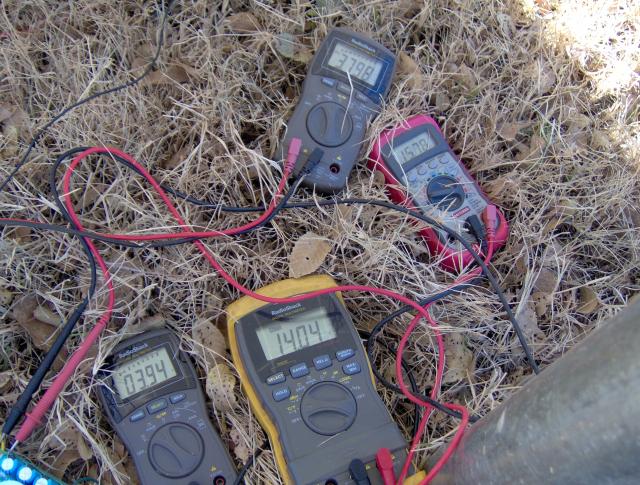
This is a picture of my MPPT working from 12V solar panel to 12V battery. This is not recommended as MPP might be below battery voltage. (92.2% efficiency)


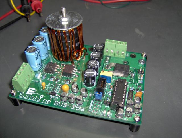
Picture of the unit not completely soldered:


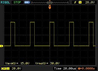
Picture of voltage across bottom side MOSFET:


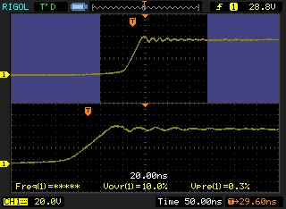
Voltage across top side MOSFET:


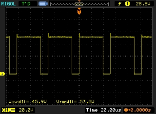
Zoom in of leading edge of above picture:


I only made 5 of them, one for me, one for a friend, one for kill-it-dead test and the other two I can spare when completely tested. The test one I will most likely give it just for the shipping because of the abuse I have given to it.


Well, hope I made my explanation clear.

« Last Edit: January 09, 2009, 08:44:01 AM by s4w2099 »

Airstream

  • Full Member
  • ***
  • Posts: 245
Re: Buck converter for micro hydro
« Reply #13 on: January 09, 2009, 08:51:20 AM »
Dibbs.
« Last Edit: January 09, 2009, 08:51:20 AM by Airstream »

Madscientist267

  • Hero Member
  • *****
  • Posts: 1181
  • Country: us
  • Uh oh. Now what have I done?
Re: Buck converter for micro hydro
« Reply #14 on: January 09, 2009, 10:23:39 AM »
Throwing two cents in here -


One thing to remember when dealing with these small amounts of power is not only monetary cost (as flux pointed out) but also its easy to get mislead by how efficient a buck/boost circuit seems to be, and it doesn't always come out in the wash. Conversion consumes power, and depending on available input, can become prohibitively expensive efficiency wise.


The less power you are able to make, the harder the efficiency hit is. In my most prevalent case, one of my bucks consumes 1.6 W when converting at full load, eating 20% of my panel's output!


You're dealing with a little more power than I am, but still might want to keep this in mind, since you're talking only 22% gain by changing to 24V.  Unless your converter is extremely efficient, your net efficiency gain would be minimal, in the few percent range, not worth the effort IMHO.


Steve

« Last Edit: January 09, 2009, 10:23:39 AM by Madscientist267 »
The size of the project matters not.
How much magic smoke it contains does !

ghurd

  • Super Hero Member Plus
  • *******
  • Posts: 8059
Re: Buck converter for micro hydro
« Reply #15 on: January 09, 2009, 11:01:08 AM »
Guessing this is a 3 phase dual rotor, wired Star?


Wire it Jerry (each phase individually rectified),

Rectifiers at the hydro,

cap on each bridge's output,

run 6 wires to the battery.  2 exist, just need 4 more, so 14-3 w/g UF-B and use the ground wire too.  Or maybe a 500' spool of #16 landscape lighting wire?


G-

« Last Edit: January 09, 2009, 11:01:08 AM by ghurd »
www.ghurd.info<<<-----Information on my Controller

boB

  • Sr. Member
  • ****
  • Posts: 389
  • Country: us
    • boB
Re: Buck converter for micro hydro
« Reply #16 on: January 09, 2009, 11:43:47 AM »


You have done a VERY nice job on your MPPT controller !


What kind of cores and FET drivers are you using ?  it looks

like your PCB has changed somewhat from looking at your other posting.


boB

« Last Edit: January 09, 2009, 11:43:47 AM by boB »

jeffbirkle

  • Newbie
  • *
  • Posts: 41
Re: Buck converter for micro hydro
« Reply #17 on: January 09, 2009, 04:48:17 PM »
Hi all.

Thanx for all your comments.


I tested charging at 24 volts, but no higher (36-48 volts). I will test that at a later date.

I can change to a 24 volt bank (and may still do so?), but I would have to buy a new 24 volt inverter, a second Solar panel, make a new stator for my wind geny, and change my back-up 12 volt 4 HP B+S gas geny using an old Chevy alternator with a modified external regulator, which charges at 20 amps at 600 RPM, using 1 LTR of fuel every 5 hours.


I should mention this is a dual rotor 3 phase, wired in star, 3 wires going to the battery bank then regulated.


The water turbine spins around 110 RPM unloaded, and 55 RPM loaded with 9 coils and 12 Neo's, so it has around 12hz? well below operating a transformer?  I do have a whole bunch of transformers kicking around and will test anyway.


I would like to build the open loop buck, but I can't seem to find any info other than a standard buck having a flywheel diode, an inductor, a cap, a mosfet, and a switching control circuit.

Being somewhat of a beginner in electronics, I need to do some more research.


Thanx again.


J

« Last Edit: January 09, 2009, 04:48:17 PM by jeffbirkle »

s4w2099

  • Full Member
  • ***
  • Posts: 234
Re: Buck converter for micro hydro
« Reply #18 on: January 09, 2009, 04:49:23 PM »
Thanks Bob,

The first version was a bang bang attempt to see if MPPT really works. I did not worried too much about making the design compact or anything. In this last version I did after I verified that MPPT is really worth it.


The cores are MAGNETICS INC KOOLMUs. I love them because they have this soft saturation characteristics which is very helpful when first developing a converter. Un like ferrite that saturates very sharp. They are more expensive than regular magnetics. There are about 7.50USD of cores in that board.


The driver is an ir21834 typically used for high voltage h bridges, so yes it is fully synchronous. This was just a test. I chose it because I am now a high voltage nut. All I need to do in order to make this device high voltage input is change the MOSFETs up to 600V and input capacitors. Right now I am working at 48V nominal input and 12V nominal output. 12V output because I would like to test the worse possible case (efficiency wise).

« Last Edit: January 09, 2009, 04:49:23 PM by s4w2099 »

ghurd

  • Super Hero Member Plus
  • *******
  • Posts: 8059
Re: Buck converter for micro hydro
« Reply #19 on: January 09, 2009, 05:54:39 PM »
"a switching control circuit" is the hard part.

All those parts use or lose a bit of power.  Easy to end up in the negative.


The 55 and 110 RPM confuses me at the moment.  

I am hydro-challenged.  Looks like it is on the cusp?

I expect Jerry Rig will work out better, and it is easy to try.

(even without the 6 wires and caps)

G-

« Last Edit: January 09, 2009, 05:54:39 PM by ghurd »
www.ghurd.info<<<-----Information on my Controller

oztules

  • Hero Member
  • *****
  • Posts: 1477
  • Country: aq
  • Village idiot
Re: Buck converter for micro hydro
« Reply #20 on: January 10, 2009, 12:00:25 AM »
or at least try it in delta (easiest)... then jerry


...........oztules

« Last Edit: January 10, 2009, 12:00:25 AM by oztules »
Flinders Island Australia

Flux

  • Super Hero Member Plus
  • *******
  • Posts: 6275
Re: Buck converter for micro hydro
« Reply #21 on: January 10, 2009, 01:34:08 AM »
The turbine is loaded about right if the load speed is half no load speed. The suggestion to change the alternator from star to Jerry connection may be worth a try, it will improve the alternator situation but will do nothing about your loss from the long line. You can use scrap cable at such low voltage safely so you may be able to beef up the line at little cost and gain from Jerry connection.


Transformers aren't even in with a chance, to run at 12Hz you will need a 240/110v transformer and unless it is several kVA the resistance will be much worse than your line. If you find one with low enough resistance then the magnetising current will probably kill your little supply.


Flux

« Last Edit: January 10, 2009, 01:34:08 AM by Flux »

tecker

  • SuperHero Member
  • ******
  • Posts: 2183
Re: Buck converter for micro hydro
« Reply #22 on: January 11, 2009, 06:25:23 AM »
Here's an easy buck circuit .I use this on the 24 volt bike to charge at 12 . The microwave primaries vary in impedance so try one from a small micro .If you build one make it byfillar and big wire you can cut taps in the microwave primary easy enough just snip at the ends and lift it out for a center tap . The Cap is mot critical over 5 K over 50 V is best


> The critical part of cutting in to the microwave primary or making a coil is the bias on the transistor .You can get the bias in the park with a 100k pot across the primary to get the transistor to turn on all the way I should have put that in there the small micro transformer I had for this task allows the transistor to turn on about 60 % witch is about right for a fast peddle .


>> I 'll switch to a larger micro transformer and add the pot to see if I can get an adjustment goin

Ok I got to get to work so I'll patch this back together to be back in perameters

 I,m in linux so Lt spice is not up here

>the resistance is a no go across the coil legs.

I'll post the whole thing as a diary after I get some adjustment other than cutting taps in the transformer .I'm working with my friend the old Lm317 as it is in the data sheet It can sit in an AC circuit and clp so I'm biasing the Adjust to current out the clip through the base of the 3055.Here's the pic as a jpeg As is you can fit it into a charge circuit by working with the coil size .sorry for the f up .


« Last Edit: January 11, 2009, 06:25:23 AM by tecker »

jeffbirkle

  • Newbie
  • *
  • Posts: 41
Re: Buck converter for micro hydro
« Reply #23 on: January 15, 2009, 05:48:44 PM »
Now that the freezing weather is here I had to pull that water turbine out for the winter. I am working on a new modified Francis style that should withstand the freezing temps, and hope to install it in 3 weeks and resume testing.


I do have a microwave primary transformer but it is out of a 1400 watt unit so I will look for a smaller one.


Thanx

Jeff

« Last Edit: January 15, 2009, 05:48:44 PM by jeffbirkle »