This is a continuation of part 2 which can be found here:
http://www.fieldlines.com/story/2007/4/26/82929/6080
Which was itself a continuation of part 1 which can be found here:
http://www.fieldlines.com/story/2007/4/20/95351/1614
In part 3, I will build a prototype of circuit 4, throw in a few component values, and at least one method of matching the leds for the parallel strings.
In part 2, we saw the necessity to match the combined Vf in each string if we want to use one current source to power multiple strings of leds. With the best of intentions, I figured that for a string of 3 leds, I could divide my batch of 100 leds into 3 piles; those where Vf was less than avg - 1sd, those where Vf was greater than avg + 1sd, and all those inbetween. According to textbook stats, I should have about two thirds of my leds in the middle pile, with the rest split evenly between the other 2 piles. My initial plan was to use one led from each pile to make each string of 3 leds. But Murphy was going to have none of that, and a change in room temperature from one day to the next meant I had 4 leds in the lowest pile, 39 leds in the highest pile, and 56 leds in the inbetween pile.
So I decided to build my sample using only leds from the inbetween pile. What I wanted was 2 strings of 3 leds. Now this is not the only way to achieve this end result; I don't even claim that this is the best way; it was simply how I chose to do it. I set up my breadboard with circuit 4,
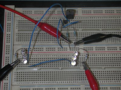
set Rs at 47 ohms to give me a total current of 11.00 mA, set Req at 47 ohms for no particular reason, and picked 6 leds at random from the middle pile to populate it. I connected a voltmeter to the lower leg of each of these equalisation resistors. If the current through each string of leds was exactly the same, the meter would show a voltage differential of zero. By swapping pairs of leds between each string, I managed to get the differential voltage down to several millivolts. I then changed Rs to 15 ohms to increase the current source to 35mA, and used 2 meters to measure the current in each led string, and was satisfied to find that the current in each string was 17.x milliamps, with a difference of approx 0.3mA. I also varied the supply voltage from 11.0 to 30.0 volts, and was satisfied to see the current change from 34 mA to 36 mA, with absolutely no discernable change in light output.
This technique of swapping leds can be expanded beyond 2 strings, with a little imagination.
Just for interests sake, I changed Req to zero, and found that the difference in the 2 currents was less than 1 mA.
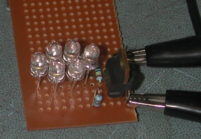
I then did a pencil layout of the components to fit it on veroboard, and built it, being careful to keep each of the 2 strings of leds together. I mounted the two equalisation resistors (Req) vertically, and in such a manner that I could use the lower legs as connection points for my voltmeter, as a final check, and confirmed the voltage differential of less than 10mV.
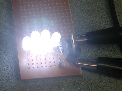
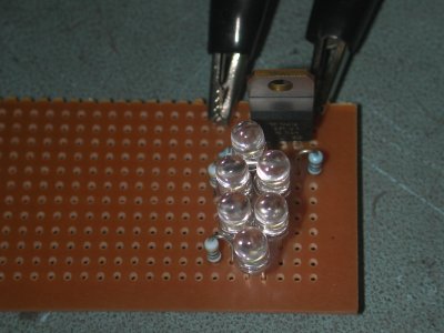
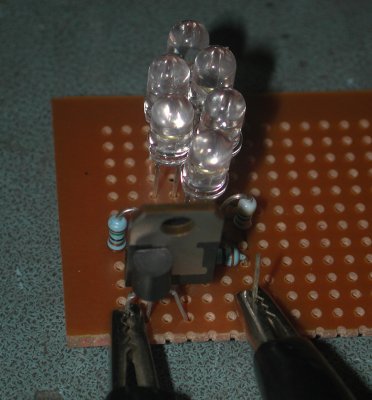
As a final check, I waved the hot-air gun at it whilst monitoring the overall current drain, to confirm the negative temperature coefficient characteristics. This is the same test I use for the 24 bit ADC's on our commercial beltweighers. Whilst not as fine grained a test as firing up the environmental chamber, it is at least a useful test, and confirmed the negative temperature coefficient, with the current dropping by several milliamps.
It would be very interesting to repeat this test on the simple single resistor setup.
In part one, I presented a number of circuits. The first 3 are interesting as an aid to understanding how we finish up at circuit 4. But circuit 4 is far superior in terms of stability, particularly thermal, with its small but very important negative thermal coefficient.
Component values for circuit 4.
from Ohm's law, R = E/I
for Rs, the voltage will be the Vbe of the transistor. At the extremely low current levels we're working at, will be a little less than the typically quoted 0.6 volt. I measured 0.525 on my prototype.
So, for 35mA, Rs = 0.525 / 0.035 = 15 ohms
Rg, is not critical. As a rule of thumb, I use 1M.
Req, again not critical. Depends on how well you can match the strings of leds, and also partially on how much headroom you give yourself between design current and maximum continuous current. If using one current source per led string, can be omitted completely.
Number of parallel strings and failure mode.
It has been my experience that;
- : when properly fed, leds don't normally fail.
- : on those rare occassions when leds do fail, they fail to open circuit.
The upshot of this is that running only 2 strings in parallel off one current source is not that good an idea. If one led fails to open circuit, that string will draw no current; and the other string will draw all the current. In the presented prototype, failure of one led would probably result in destruction of the 3 leds in the other string. Good thing leds don't normally fail very often. Once one got past 3 or 4 parallel strings, it would be possible to leave enough headroom between design current and max continuous current, that failure of one string wouldn't push the other strings beyond their maximum current. But that's one of the things that has to be weighed up on a case by case basis; whether the small savings in component count is worth the risk versus using a seperate current source for each string. There is no one perfect solution for all applications.
I know this series started out as a two part series, and this is already part 3; but in part 4 (which will probably be a diary entry) I will hopefully present a slightly more ambitious led light. Running off 24 volts, multiple strings each of 6 leds with individual current sources, built on veroboard, stacked, with the leds mounted edge on, stuffed inside a small jiffy box. Just need a gooseneck or articulated arm and I'll call it a desklamp.
Amanda
