Author Topic: steel backing of magnets  (Read 3586 times)

0 Members and 1 Guest are viewing this topic.

mr mills

  • Newbie
  • *
  • Posts: 5
steel backing of magnets
« on: September 25, 2007, 08:33:38 PM »
Hi,


First of all, i'm a newbie, so apologies if this subject was already handled earlier.


I'm trying to get some more theory/reasoning about why i should or shouldn't use a steel disk to place the magnets on for my alternator. I'm building an axial rotor, mounting the magnets on a rim of a bicycle wheel. So basically, no steel or other fieldline conductors are close to the magnets.


My impression is that steel disks are often used to "arrange" fieldlines, so more of them effectively cross through the coil wires. Now, i can understand this concept when it is used along with laminated steel cores in/behind the coils in the stator, or when a second magnet disk is used behind the coils, attracting the fieldlines straight through the coils.


But suppose i'm using air coils on the stator(which can have it's advantages), is there still a benefit in using a steel base for the magnets on the rotor?


I think my bicycle wheel design can be compared slightly with the "wooden alternator", no fieldline conductors in rotor nor stator, and using "overkill" rare earth magnets. I think the output of my 24inch bicycle wheel could be reasonable, because it makes a high passing speed of the magnets at low RPM. In the end i would like to apply the alternator for a savonius type wind turbine.


mr mills, The Netherlands.

« Last Edit: September 25, 2007, 08:33:38 PM by (unknown) »

electrondady1

  • SuperHero Member
  • ******
  • Posts: 3122
  • Country: ca
Re: steel backing of magnets
« Reply #1 on: September 25, 2007, 08:26:55 PM »
 been collecting parts and kicking around the same idea for a while,now probably waisted about 1/2 an hour on it today.

look for a steel wheel to start with.

mine's 20" in dia.

so twenty x3.14 would give a circumference of 62.8"

it might be a good home for all the hard drive mags i've been saving

they render a pole width of about .75"

so with  50/50 mag spacing it should be possible to fit in 42 poles


using an aluminum wheel is pointless


this metal is rather thin and and only rather thin mags could be used unless you some how build up the amount of steel beneath the mags

the steel backing is required to concentrate and focus all the flux in one direction .


the profile of the rim is complex but it may be possible to  form a bent pole and coil configuration in order to get some leg length.

good luck!

« Last Edit: September 25, 2007, 08:26:55 PM by electrondady1 »

mr mills

  • Newbie
  • *
  • Posts: 5
Re: steel backing of magnets
« Reply #2 on: September 26, 2007, 06:40:17 AM »
Oops,


As you may have guessed, i'm actually using an aluminium rim. Next to that i've constructed aluminium shoes to fit the magnets in.


But i had a (very) good reason to use an aluminium rim! Truing a steel wheel is much harder than truing an aluminium wheel. (Yes, i'm a wheelbuilder also..) You can make an alumium wheel much better circle-shaped, reduce sideway-whobbles to less than 1/10th mm.


The magnets are placed in prepared alu shoes that are fixed along the side of the rim, so not "on top" of the rim. So when the wheel is flat facing the ground, vertical wheel axis, the magnets (fieldlines) are also facing the ground. Coils will be placed on a big stator board. A nice flat wheel will result in a nice constant and small airgap.


This combined with the facts of wooden alternators (which even have a much smaller diameter), i still hope to get sufficient output. If not, i'll set up an identical wheel but than with everything made out of conductive steel.


Mr mills

« Last Edit: September 26, 2007, 06:40:17 AM by mr mills »

disaray1

  • Full Member
  • ***
  • Posts: 196
Re: steel backing of magnets
« Reply #3 on: September 26, 2007, 07:00:14 AM »
Mr Mills-


 I think you'll find that your alu rotor will work, but quite poorly. Steel is used to create the circuit for flux to travel- no steel, no circuit. AND, a steel bike wheel is really to thin of metel to get the job done effectively. Note that most of the axial flux machine built here are constructed using thick steel discs, say, 8 to 12mm. With strong magnets, you'll need this much steel to contain and channel all of the flux.


 Have fun....


 David

« Last Edit: September 26, 2007, 07:00:14 AM by disaray1 »

TomW

  • Super Hero Member Plus
  • *******
  • Posts: 5130
  • Country: us
Re: steel backing of magnets
« Reply #4 on: September 26, 2007, 08:31:26 AM »
mr;


Well, I wish Dan would put a large disclaimer on those wooden alternator pages clearly stating that while they "work" they are not a good choice at all.


I do not understand why you claim Al is easier to true than steel? I have no idea what you mean by "I am a wheelbuilder" just seems you are putting some unrealistic limits to your construction.


You must be limiting yourself to some ingrained process to make wheels. In fact, wheels is probably a bad analogy anyway. You need disks of iron to really make it work and be worth the time, effort and resources.


I would strongly suggest that you drop your preconceptions of how these things work and do some research before you limit yourself to some preconceived ideas on how it is done. It is your time and resources but I felt I had to point these things out.


Cheers.


TomW

« Last Edit: September 26, 2007, 08:31:26 AM by TomW »

finnsawyer

  • Hero Member
  • *****
  • Posts: 1565
Re: steel backing of magnets
« Reply #5 on: September 26, 2007, 08:48:53 AM »
You need to put a substantial iron 'hoop' under the magnets and another substantial larger diameter iron 'hoop' behind the coils to form the magnetic circuits.  Why?  With a VAWT you want as low a cut-in RPM as possible.  That means you might want 1/2 the cut-in RPM.  Well, in going from a 16 inch rotor to say  a 32 inch wheel you have only doubled the speed.  To effect cut-in at half the RPM you still need the same strength of magnetic flux as with the 16 inch rotor.  So, you need the same effective magnetic circuits.
« Last Edit: September 26, 2007, 08:48:53 AM by finnsawyer »

finnsawyer

  • Hero Member
  • *****
  • Posts: 1565
Re: steel backing of magnets
« Reply #6 on: September 26, 2007, 09:02:02 AM »
A little add on here.  With twice the diameter you can double the number of magnets and push the cut-in RPM down farther, but note you also double the number of coils and double the resistance.  The bottom line is that without putting in the iron for the flux path you are just fooling yourself.
« Last Edit: September 26, 2007, 09:02:02 AM by finnsawyer »

DanB

  • Global Moderator
  • SuperHero Member
  • *****
  • Posts: 2151
  • Country: us
    • otherpower.com
Re: steel backing of magnets
« Reply #7 on: September 26, 2007, 02:50:03 PM »
I believe we do have such disclaimer at the top of all our older pages...  basically something saying something along the lines of 'it worked' but we do things very differently now.  I may have missed some though - it gets hard to keep up with some times ;-)
« Last Edit: September 26, 2007, 02:50:03 PM by DanB »
If I ever figure out what's in the box then maybe I can think outside of it.

mr mills

  • Newbie
  • *
  • Posts: 5
Re: steel backing of magnets
« Reply #8 on: September 26, 2007, 03:02:39 PM »
Hi again,


Wow, a lot of advice. I realize i should have thought of steel/iron backing at an earlier stage of my project.


Not being stubborn, but merely following the "course of experimental science", i will first finalize my actual design, simply because my rotor contruction is nearly finished and would be a shame to never use it. I'm not easily discouraged by disappointments, so..


I only need to glue the magnets into the shoes. The other part, the stator, will be prepared very well for placing/replacing coils or housing a replacement pmg rotor disk. The whole design is experiment-prepared, nothing's permanent! (except my glued NeoDymium magnets, ouch)


Of course i will do a 1-coil test first, trying out coil shape, amount of turns, metal/no metal behind the coil.


Let's say that i would be happy with 1.4V at something between 50-80 rpm. If that doesn't work, i'll think of something else, still using a wheel though.


Still, the idea of using air-filled coils keeps appealing to me, simply because of easy start up. Using metal near the coil: you can imagine a bigger diameter rotor with "sticky" magnets on the outer rotor edge will require more torque than usual to move it out of start position.


Anyway, my ambition is not/ never was to run the whole household on a windmill. I would be delighted if i can save enough power throughout the day to run some lights in the living room at night, and maybe even watch our small lcd TV.


That's it for now! Thanks a bunch!


(Please keep on advising me, i can have it..)

« Last Edit: September 26, 2007, 03:02:39 PM by mr mills »

Bruce S

  • Global Moderator
  • Super Hero Member Plus
  • *****
  • Posts: 5413
  • Country: us
  • USA
Re: steel backing of magnets
« Reply #9 on: September 26, 2007, 03:38:16 PM »
mr mills;

  In what part of the Netherlands are you? close to Amsterdam or other directions?

There are a fair number of Velomobile builders located in Velsen that turn out some high quality units.

I was wondering, that since one your plans was to possibly use it as a VAWT; what your plans were for the hubs and the different loads the bearing are going to be experienceing?


Bruce S

« Last Edit: September 26, 2007, 03:38:16 PM by Bruce S »
A kind word often goes unsaid BUT never goes unheard

vawtman

  • Hero Member
  • *****
  • Posts: 1425
Re: steel backing of magnets
« Reply #10 on: September 26, 2007, 04:40:02 PM »
Hi Mr Mills


 Any chance of a pic of your nearly completed rotor?


 You can make a radial that would start easily with steel backing on both sides.


 What would you do with 1.4 volts?

« Last Edit: September 26, 2007, 04:40:02 PM by vawtman »

hiker

  • Hero Member
  • *****
  • Posts: 1661
  • BIG DOG
Re: steel backing of magnets
« Reply #11 on: September 26, 2007, 05:57:21 PM »
fill that rim gap with some steel strapping--should help out on your mags..

make a ring out of some steal strapping as well and toss that under your coils..

your output power will be a lot higher..and the small amount of drag will be offset by the increase in power..

ps: for the coil -ring--tape one side of the strapping before you wind it..

    you could even aneal that strapping before you wind it..just toss it in a

    fire or grill... good luck..

« Last Edit: September 26, 2007, 05:57:21 PM by hiker »
WILD in ALASKA

CmeBREW

  • Hero Member
  • *****
  • Posts: 615
Re: steel backing of magnets
« Reply #12 on: September 26, 2007, 07:48:22 PM »
Like you said, the important thing is to not ever get discouraged , but keep learning the principles and experimenting and having fun. You WILL make something that pays off. If you could perhaps show a picture, some here might have some more good suggestions to get more power out of it. I like Hiker's idea of the steel straps, or you might even think of using many wraps of thin gauge steel wire around the rim and epoxy in place?? A picture would help us visualize. If you could get some kind of steel behind those magnets and have the steel connect around the whole circle of magnets somehow, it would probably DOUBLE the power output. And you need all the help you can get with a slow RPM VAWT. It is also good that your expectations are quite accurate and reasonable. Keep working at it!!
« Last Edit: September 26, 2007, 07:48:22 PM by CmeBREW »

mr mills

  • Newbie
  • *
  • Posts: 5
Re: steel backing of magnets
« Reply #13 on: September 27, 2007, 09:20:43 AM »


Ok, i hope the pictures will appear ( i can't see them while i'm typing). Just a summary of what i want to make: rotor, 18 magnets, stator 27 coils, 3phase system. When i mentioned 1.4V earlier: that's what i want to achieve per coil, at relatively low rpm


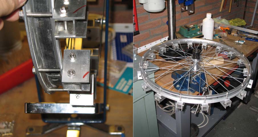
Anyway, thanks again for info & support until now. The picture shows a close look at "the magnet shoe" which will fit exactly for an axially magnetized NeoDymium magnet, 40*20*10mm. If it is glued in the shoe, only the necessary surface is exposed (except for the outer ends). The other pic shows the whole wheel in my vice, but in the position it will be used, axis vertical, magnets facing down. I won't show you any stator pictures yet, because it's a dull picture, just a plain board, with a self made flange in the middle, no coils made yet. Bearings & stuff is a story for later, i have some ideas, but first things first.


As you see, i've used box-shaped aluminium tube, cut into pieces of 40mm, drilled mounting holes for the screws. The sides (red marked) are also aluminium, sticking out just under 10mm, to "clamp" the magnets in place.


The rotor will house 18 magnets/magnet shoes so i drilled 18 wholes straight through the rim sides (before the wheel was spoked!). I did 18 max, because otherwise the sturdy spoked wheel will collapse under the spoke tensions.


I may still finalize this contruction (as in the picture), glue in the magnets etc. and prepare for the the worst, OR..


Just a thought:


I can remove the shoes, disassemble them, use same sized steel boxes instead of aluminium, re-attach the aluminium side shoulder plates (no steel for that, as it will short-circuit fieldlines from coilfacing magnet end to back end)...


The next step is a tricky one: Instead of re-attaching the new completed shoes straight onto the alu wheel rim again, i could make a thick steel bed (40mm wide, approx. 100mm long, 4-5mm thick), drill two wholes according the whole-whole distance on the rim. So have this steel bar beneath each magnet shoe pair. This will create a horse-shoe magnet effect over two adjacent magnets. Multiply this action by 9, and my wheel will contain 9 separate "horse-shoe" magnets. It will at least arrange some of the fieldlines. I haven't yet calculated what it would do to a 3phase coil arrangement, but maybe that's not something to worry about now.


My intention still is to keep a "light" rotor, no too much mass to accelerate, also for not running a risk of having too much weight on the outer edge of a large diameter rotor, making it more vulnerable for bending and hitting the stator.


I think this may be a good compromise between steel mass and a lightweight rotor; Do you think? Objections? Recommendations?


mr mills


« Last Edit: September 27, 2007, 09:20:43 AM by mr mills »

hiker

  • Hero Member
  • *****
  • Posts: 1661
  • BIG DOG
Re: steel backing of magnets
« Reply #14 on: September 27, 2007, 02:34:20 PM »
okay......

try just putting a flat piece of metal under each mag..

you dont want to  bury your mags in metal--you need the sides and top exposed..

could even chop some steal strapping tolength and add under each mag.[4 layers or more]

« Last Edit: September 27, 2007, 02:34:20 PM by hiker »
WILD in ALASKA

wooferhound

  • SuperHero Member
  • ******
  • Posts: 2288
  • Country: us
  • Huntsville Alabama U.S.A.
    • Woofer Hound Sound & Lighting Rentals
Re: steel backing of magnets
« Reply #15 on: September 27, 2007, 05:18:46 PM »
I would have placed the magnets inside of the Wheel frame facing away from the axle. That way you don't need the Magnet Boxes that you made. Then the Coils would be in a circular stator around the outside of the wheel where the Tire would be. I guess that would make stator construction more difficult tho.
« Last Edit: September 27, 2007, 05:18:46 PM by wooferhound »

CmeBREW

  • Hero Member
  • *****
  • Posts: 615
Re: steel backing of magnets
« Reply #16 on: September 27, 2007, 08:38:50 PM »
MrMills,

     Nice looking work so far. Yeah, it would be much better to try 'steel boxes' and steel 'horse-shoe' connectors,,, If I understand you right that is. Any attempt to connect the circle of magnets with steel is MUCH better than having each magnet all alone in alumimum. Those 'Wooden alternators' Dan made in the beginning had pretty big magnets that were butted up very close to each other. The flux and field lines connected in the AIR fairly good.  Thats why he got a fairly good output. But as he said, it is still a "poor magnet circuit" since the back of the mags were not stickin to a steel center. He may have got twice the output if he had. But your mags look like they have a 3" air gap distance to one other. Even the field lines can't connect at all, so it will have probably less than half the power it should.  I should know, I actually made a 'wooden alternator' last year. (plywood rotors) Needless to say, It didn't turn out so good. So try your best to somehow connect the mags with some steel. Also, try to have the mags actually stick on the steel with NO air gap between the mag and steel. Trying to rivet pieces of thin steel together is not as good as SOLID steel all the way around. (But it is better than AIR, wood, or aluminum!)   -Hope it works out!
« Last Edit: September 27, 2007, 08:38:50 PM by CmeBREW »

mr mills

  • Newbie
  • *
  • Posts: 5
Re: steel backing of magnets
« Reply #17 on: September 28, 2007, 12:53:05 AM »
But the difference with "conventional" fluxpath constructions would be that i'm only coupling two adjacent magnets, 1 north to 1 south. Not interconnecting all magnets in the complete circle. This will save steel mass in the rotor. Wouldn't that suffice to make at least a flux circuit through a pair of adjacent magnets?


That's what i meant with "horse-shoe magnets", the old fashioned bent bar of steelmagnet: consider the outer ends as the magnets, and the rest of the steel is the connector between them.


Mr wooferhound: As for the shown construction, i decided to have the shoes on the flat side of the rim, because the side of the rim can be trued dead-flat. The outer-rim is harder to get into circle-shape, theres always a whobble remaining there somewhere. And indeed, stator construction would be harder to make.


mr mills

« Last Edit: September 28, 2007, 12:53:05 AM by mr mills »

TomW

  • Super Hero Member Plus
  • *******
  • Posts: 5130
  • Country: us
Re: steel backing of magnets
« Reply #18 on: September 28, 2007, 07:05:22 AM »
mr;


Please do not mistake me for any kind of expert. I am more of a harvester of information.


Because you asked:


But the difference with "conventional" fluxpath constructions would be that i'm only coupling two adjacent magnets, 1 north to 1 south. Not interconnecting all magnets in the complete circle. This will save steel mass in the rotor. Wouldn't that suffice to make at least a flux circuit through a pair of adjacent magnets?


It seems to make sense. However, [seems to always be a however] each adjacent magnet needs a flux circuit to it's partner.


You will still end up with a continuous band of steel. Or segments, whatever. Properly balanced mass in the rotor should not be a big factor especially once things get moving. Within reason.


See the point I am making?


WRT the magnets mounted to the side of the rim, I think it will be very marginal on stiffness once the attraction / repulsion of a working stator / magnet rotor combination. This can create a substantial and sometimes violent vibration that is from the magnet and coils wanting to be together as the induced coil voltage creates a magnetic field.


It is good that you are trying things for sure but I think you need to rethink some of your design if you expect it to be be useful long term.


The other thing is that a lot of bike parts are pretty cheap and not designed for odd loads like the sideways  pulling force that rim will be subjected to many times per revolution. I realize there are quality bike parts around, also. The not designed for it part still applies to those.


None of this may matter if you are just doing it for fun or to learn. In fact, failure can often teach us more than success.


Cheers.


TomW

« Last Edit: September 28, 2007, 07:05:22 AM by TomW »

electrondady1

  • SuperHero Member
  • ******
  • Posts: 3122
  • Country: ca
Re: steel backing of magnets
« Reply #19 on: September 28, 2007, 08:29:41 AM »
 mr. mills

may i suggest before you go much further you google search the board using the name

electric ed

 in his files you will find several colored diagrams explaining how electricity is generated .


you have gone to  a lot of work and built and interesting mechanism.

but it is not well suited to produce energy for several reasons.


if you have already purchased the magnets you require for your device then by all means put them in place and do a test coil.

just don't glue then in .

i think you may have difficulty in obtaining 1.4 volts from a coil with this configuration.

you really have come to the right place in order to learn

i had zero knowlege of electrical generation when i discovered this sight about 3 years ago. and have learned so much and have had a lot of fun experimenting.

good luck !

« Last Edit: September 28, 2007, 08:29:41 AM by electrondady1 »

TomW

  • Super Hero Member Plus
  • *******
  • Posts: 5130
  • Country: us
Re: steel backing of magnets
« Reply #20 on: September 28, 2007, 08:51:27 AM »
Link to Electric Ed's stuff here:


http://www.fieldlines.com/?op=user&nick=electric+ed&tool=info


Cheers.


TomW

« Last Edit: September 28, 2007, 08:51:27 AM by TomW »