Author Topic: My first coil design for testing  (Read 1395 times)

0 Members and 1 Guest are viewing this topic.

Roly SA

  • Newbie
  • *
  • Posts: 27
My first coil design for testing
« on: January 29, 2008, 08:55:51 PM »
Hi All


Firstly, excuse the intro, i had a Roger Waters song in my head when i wrote that.


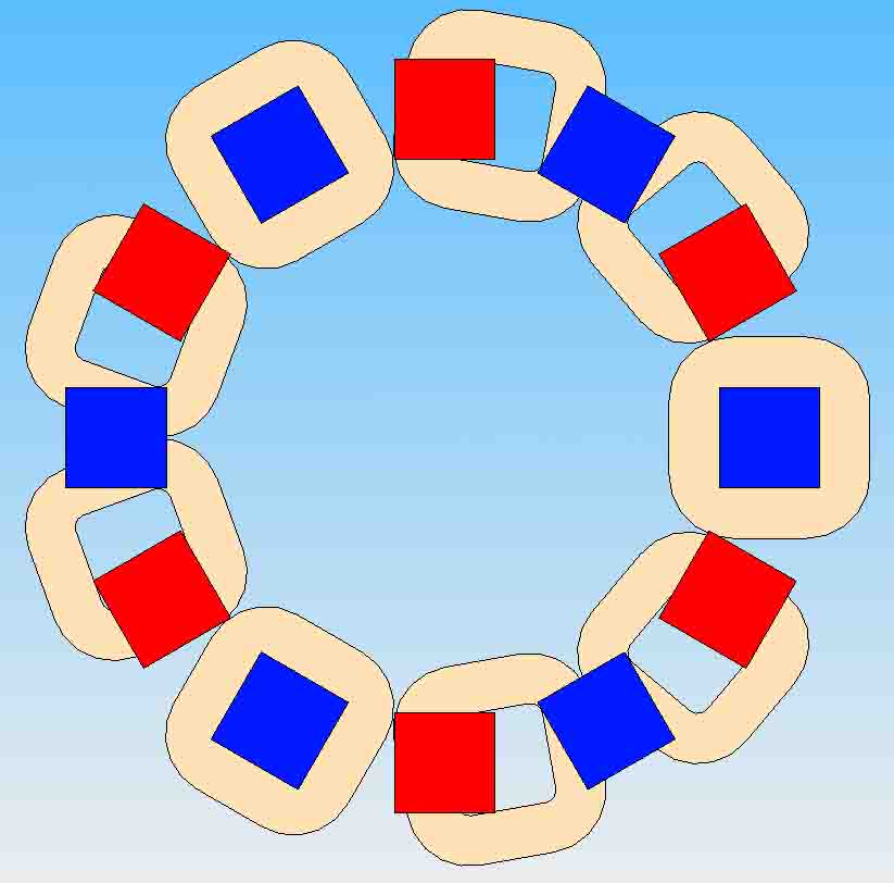
So my basic design is a 9 coil, 12 pole design. From what ive gathered, the sane thing to do is to have the hole in the coil the same size as your magnet. The magnets i plan on using are 40 x 40 x 10 mm, so about 1.5 x 1.5 x.0.5 inches N35 Neos. The inside of the coil will be a 40 x 40 square, and the windings will bring it to about 80 x 80 mm once done. Thickness im aiming for is about 10mm, same as magnet thickness.


If the north pole of one magnet moves out of the centre of the coil in a clockwise direction, the south pole of the following magnet should just start moving over the same coil. A north pole moving over 1 side of the coil, and a south pole moving over the other side of the same coil will cause the flow of electricity in the same direction in the coil.


The coils i want to wind with 0.5mm wire, 2 strands in hand.The reason for 2 strands is to get the total length of copper with half the resistance, as the electrons dont have to move the total length of the wire. I have worked out that i will get about 800 turns of wire in the coil, adding up to about 208 m of copper if my calculations are correct.


The whole stator will fit inside a 360mm diameter circle, and the rotors will be about 300 mm OD.


I have a good idea on how i want to mount and balance the setup, which requires a few machined parts. So hopefully it will all go OK.


Here is a pic of my coil and magnet layouts. Blue is north pole and red the south. The coils are copper in colour should it not make any sense.


Please tell me what you guys think. Will i get something decent out of it?


Thanks for your input


Roly SA


« Last Edit: January 29, 2008, 08:55:51 PM by (unknown) »

TomW

  • Super Hero Member Plus
  • *******
  • Posts: 5130
  • Country: us
Re: My first coil design for testing
« Reply #1 on: January 29, 2008, 02:34:13 PM »
Speaking of Roger Waters, I am amused to death.


Sorry, couldn't come up with anything on topic to say except regarding Roger Waters.


Cheers.


TomW

« Last Edit: January 29, 2008, 02:34:13 PM by TomW »

Tritium

  • Hero Member
  • *****
  • Posts: 658
Re: My first coil design for testing
« Reply #2 on: January 29, 2008, 05:35:39 PM »
800 turns of wire per coil? Seems off by a factor of 10 for most designs built here. What voltage are you shooting for?


Thurmond

« Last Edit: January 29, 2008, 05:35:39 PM by Tritium »

Flux

  • Super Hero Member Plus
  • *******
  • Posts: 6275
Re: My first coil design for testing
« Reply #3 on: January 30, 2008, 02:07:34 AM »
Layout looks fine. You don't give a voltage or prop size so it is not possible to comment on the number of turns.


I don't follow the logic of the two wires in hand unless you are forced to use that wire size. Given a choice of wire size you can get the same resistance with a single wire.


If you mean 800 turns per phase then possibly!. If you are looking at 800 turns per coil then you are into a higher voltage than most people. Even if you are muddled over this 2 in hand winding and you mean 400 turns per coil then it is still high.


Come back with prop size ( or cut in speed) and intended voltage if you need help.


Flux

« Last Edit: January 30, 2008, 02:07:34 AM by Flux »

Roly SA

  • Newbie
  • *
  • Posts: 27
Re: My first coil design for testing
« Reply #4 on: January 30, 2008, 03:35:08 AM »
I took the cross section area of the coil, which is 10mm x 20mm. Working with 0.5mm diameter wire, you would get 20 strands per layer, and about 40 layers to fit in the cross section.


I havent taken into account the thickness of the coating on the wire, as well as any factory variations on thickness, so the coil might be a bit larger, maybe 11 x 23mm. But this is not the worry i have.


I found that i made a mistake in my length calculations. After fixing my spreadsheet, i got the estimated length of copper in the coil to be about 219m, which is 11 m more than i had initially.


Not sure yet how to calculate the voltages, so i want to do a test coil first, and get some voltage measurements off that. Will be interesting to see what it will be. Also have a few rotor speeds i want to test it on. If the coil performs well, i will wind 8 more, then make a temporary stator to see what the overall performance is.


The magnets are N35 neodymiums, as this is the strongest ones i can get hold of here in South Africa. Still trying to get the technical specifications off the supplier to get gauss values and flux densities. Once i have them i will post it here for all to see, and maybe see if they will be any good.

« Last Edit: January 30, 2008, 03:35:08 AM by Roly SA »

Roly SA

  • Newbie
  • *
  • Posts: 27
Re: My first coil design for testing
« Reply #5 on: January 30, 2008, 05:01:10 AM »
On second thought, i think i will do some testing with 1mm diameter wire instead. So i will get 10 windings per layer, and 20 layers in total, adding up to about 42m of wire. Single strand of course.


I am aiming to charge a 48v battery bank, so hopefully i can get more Vs than that.


This will be directly coupled to small 50cc bike engine i have laying around so expect to have it turning at around 100rpms.

« Last Edit: January 30, 2008, 05:01:10 AM by Roly SA »

Flux

  • Super Hero Member Plus
  • *******
  • Posts: 6275
Re: My first coil design for testing
« Reply #6 on: January 30, 2008, 07:03:12 AM »
I think your maths will be way off if you work from the theoretical area to decide the number of turns. In real life you will do well to get 60% stacking factor.


Probably 1mm would be a good size for test coils. That 100 rpm seems extremely slow for an engine drive so you may well need larger numbers of turns than normal to get 48v.


I suspect you will need about 150 turns per coil to get a cut in at 100 rpm so probably  your alternator is not going to be powerful enough to give you much output at 100 rpm. It will have a fair bit of resistance. My guess perhaps 200 turns may do it at manageable efficiency with that little engine. You ought to be looking at much higher speed.


Flux

« Last Edit: January 30, 2008, 07:03:12 AM by Flux »

electrondady1

  • SuperHero Member
  • ******
  • Posts: 3121
  • Country: ca
Re: My first coil design for testing
« Reply #7 on: January 30, 2008, 07:32:19 AM »
you have an understanding of the geometry and mag /coil relationships

build your rotors and do a test coil with some used or scrap wire .

don't  commit to a roll  of copper before necessary.


  1. rpm is very slow for a motor driven alternator.
  2. /400 turns per coil is a lot!

« Last Edit: January 30, 2008, 07:32:19 AM by electrondady1 »

finnsawyer

  • Hero Member
  • *****
  • Posts: 1565
Re: My first coil design for testing
« Reply #8 on: January 30, 2008, 09:21:47 AM »
Winding the coils two in hand with the same wire and connecting the windings in parallel gives you 1/4 the resistance not 1/2.  While 400 turns is theoretically correct ignoring the possibility of 'close packing', it's not likely you'll get that density anyway due to the problem of going around the corners.  Look at some of the pictures of actual stators.  For rectangular magnets the coils end up oval.  In your case they will tend to become circular.  You ask whether you will get decent output.  It's likely that you will end up with a high voltage low current alternator.  You don't specify what voltage you are shooting for.  Definitely do a test coil.  If you are stuck with the wire you have you may be able to go to 3 or 4 in hand with 1/9 or 1/16 the resistance of the single 800 turn strand.  Well, I wouldn't expect to be able to get the same amount of wire in the same space in those two cases, though.
« Last Edit: January 30, 2008, 09:21:47 AM by finnsawyer »

Roly SA

  • Newbie
  • *
  • Posts: 27
Re: My first coil design for testing
« Reply #9 on: January 31, 2008, 02:39:16 AM »
Thanks for all the input guys, its really appreciated.


The little 50cc bike engine i want to connect to the alternator via pullies, so i can get the rotational speed up to 500 rpm if needed, the engine just revs a bit higher. i can change the muffler on it to decrease the sound, so i have a lot of rpm to play with. Lets say for the beginning i can work on 300rpm rotor speed?


I was thinking of getting some quickset epoxy to glue the coil layers one by one. What i mean is after you wind the first layer, coat it completely with thin layer of epoxy, then do layer number 2, then let it set and repeat again. this will hopefully give a near perfect square shape. Would this idea work, apart from extending the time it takes to wind a coil by lots?


This will be the first time im winding a coil, so apologies if i was a bit optimistic with the calculations of the windings on it. So what should i be aming for if going with 300rpm. Let say 300rpm will be the peak efficiency speed im looking at. i dont realy want to change the size of the stator more than a diameter of 360mm, as this will defeat the purpose of my design. (It needs to fit in a small chest that will have vents for airflow, but prevent water getting in.)


PS - i want to use 1mm wire, as i dont want any issues with the coil heating up at that speed, but if you recommend with a thinner guage and more windings i can test that as well.


So my idea of going 2 in hand to get the resistance down was not so far fetched. i forgot to mention i will be joining them in parralel.


Awaiting your replies.


Roly SA

« Last Edit: January 31, 2008, 02:39:16 AM by Roly SA »

Flux

  • Super Hero Member Plus
  • *******
  • Posts: 6275
Re: My first coil design for testing
« Reply #10 on: January 31, 2008, 08:33:49 AM »
If you have a tiny 50cc engine and you are holding speed down to avoid noise then I have no real idea what power you will get from it so it really becomes impossible to give much advice on the alternator.


Don't waste hours trying for a perfect theoretical winding, it will only be 5% better than something you throw together in 5 minutes. Rapid epoxy is virtually useless above 80C so if you are expecting to use the wire at sensible temperatures your epoxy will be the limiting factor. Crude and crappy potting in polyester will give you a better stator. Vinyl ester is even better but hardly worth the expense for a first trial. There are reasonable temperature grade epoxies but very costly, I wouldn't use epoxy for stators.


I really can't see much point in spending time on designing you a winding when we haven't the foggiest idea what your engine can do. I suggest you wind some coils with the 1mm wire and do a trial. Perhaps try 100 turns of 2 in hand per coil. You should be able to fiddle your pulleys to cover a fair range of speed.


I suspect that winding may out perform the engine.


Flux

« Last Edit: January 31, 2008, 08:33:49 AM by Flux »

Roly SA

  • Newbie
  • *
  • Posts: 27
Re: My first coil design for testing
« Reply #11 on: February 06, 2008, 06:39:47 AM »
Woohoo


Im getting the roll of wire i have ordered tomorrow. So i will do my first coil test winding this weekend.


I have an idea for the winding jig i want to make, so will get started on building it today.


Will post a photo as soon as i can.


Wish me luck.


Roly SA

« Last Edit: February 06, 2008, 06:39:47 AM by Roly SA »

Roly SA

  • Newbie
  • *
  • Posts: 27
Re: My first coil design for testing
« Reply #12 on: March 25, 2008, 07:51:43 AM »
So my initial plan for the winding jig did not work so well. I had wooden coil shaper, and it cracked when i tightened the bolts holding it together.


Then i found some perspes/plexiglass sheeting of about 3mm thick. I glued 2 of the sheets together with some super glue to give some rigidity for the sides, then cut them out for the sides of my coil shaper.


I used 2 x 5mm sheets glued together to give me the 10mm spacer i want between the sides. The premise of my coil is based on using 4 x 6mm bolts in the corners of my intended 40x40mm square inside dimensions. The spacer is about 38x38mm, and fits inbetween the 4 bolts.


The spacer was glued to one of the sides in the correct location, and i used a drill press to drill the holes for the bolts, as well as a larger hole in the middle to hold the whole assembly while turning.


I still have to cut some slots in the sides to be able to wrap some tape around the coils to keep them together, but will hopefully have that done by the weekend.

« Last Edit: March 25, 2008, 07:51:43 AM by Roly SA »