Author Topic: Induced losses and deminishing return  (Read 285 times)

0 Members and 1 Guest are viewing this topic.

rotornuts

  • Hero Member
  • *****
  • Posts: 537
Induced losses and deminishing return
« on: May 31, 2005, 08:30:21 PM »
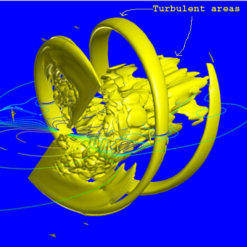
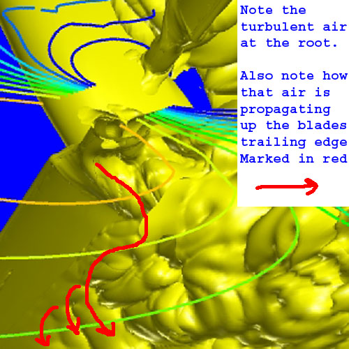
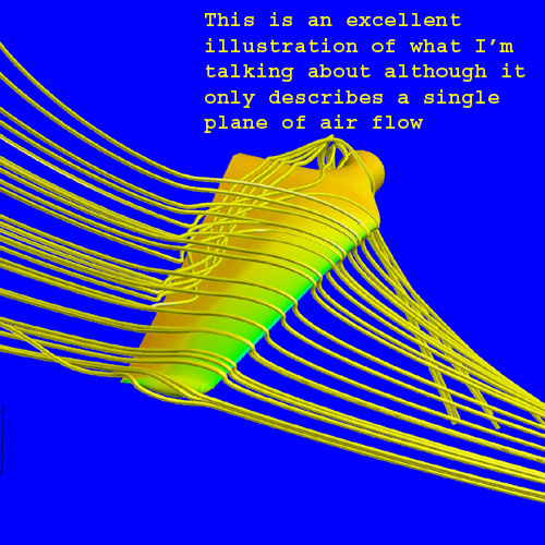
Below is some illustrations of induced losses. The images are computational fluid dynamics models done by Risoe. This is an extension of what I had to say in the last paragraph of Ed's recent blade calculation post.


http://www.fieldlines.com/story/2005/5/30/15179/7889


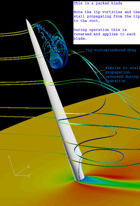
The newest enercon blade design reflects a recognition by them of the fact that treating theses areas will yield appreciable results. Note enercons use of winglets and a deep swept back root at a high angle.


http://www.enercon.de/www/en/rotorblattkonzept.nsf/mainView/1?OpenDocument


I, as usual these days, was advocating the use of fewer blades if possible and thought I would throw out some info to support my logic, which is, everytime you add another blade you add another "set" of these induced loss areas which may be greater than the losses incured by increasing the cord width of fewer blades which results in increased drag across the lifting portions of those blades.


Any takers? This isn't intended to be a classic 3 blades Vs. issue.


Mike

« Last Edit: May 31, 2005, 08:30:21 PM by (unknown) »

rotornuts

  • Hero Member
  • *****
  • Posts: 537
Re: Induced losses and deminishing return
« Reply #1 on: May 31, 2005, 02:52:37 PM »
This also reflects on my feelings about utilizing sectional L/D figures when calculating rotor Cp and torque. You need to take these areas into account. rduce your figures accordingly(penalty depends on design).
« Last Edit: May 31, 2005, 02:52:37 PM by rotornuts »

XRay

  • Jr. Member
  • **
  • Posts: 61
Re: Induced losses and deminishing return
« Reply #2 on: June 01, 2005, 04:31:45 AM »
Nice illustrations rotornuts.


These turbulent areas in illustration 2 made me think about the separation of the Laminar boundary layer. The angle of attack of the wing at the turbulent areas is mush bigger that the rest of the wing, causing this separation.

So what you need to do is to maintain the Laminar boundary across the wing.


Here a site about skin friction: http://142.26.194.131/aerodynamics1/drag/Page3.html

And here a site about one of the many solutions, creating numerous small high-speed vortexes: http://www.airshowfan.com/researchaircraftn.html


I am neither a rocket scientist nor a wing designer, so I could be very wrong about this turbulence stuff.


Greetings,

Ray

« Last Edit: June 01, 2005, 04:31:45 AM by XRay »

rotornuts

  • Hero Member
  • *****
  • Posts: 537
Re: Induced losses and deminishing return
« Reply #3 on: June 01, 2005, 08:39:01 AM »
Thanks Ray. I could always be wrong as well with regards to how much these problems are deminishing performance and wheather sectional drag is better or worse. The swail at the trailing edge of alot of laminar flow airfoils is there to reduce sectional drag. Unfortunately I'm doubting how effective a laminar flow airfoil is for a small wind turbine.


Mike

« Last Edit: June 01, 2005, 08:39:01 AM by rotornuts »

rotornuts

  • Hero Member
  • *****
  • Posts: 537
Re: Induced losses and deminishing return
« Reply #4 on: June 01, 2005, 08:47:51 AM »
Hello again Ray. I looked at the links and esspecially liked the second. I had previously mentioned using slots/slats to improve stall angle but later learned about VG's and surface roughness. That second link speaks to my concern about using laminar flow airfoils for turbines.


Mike

« Last Edit: June 01, 2005, 08:47:51 AM by rotornuts »

finnsawyer

  • Hero Member
  • *****
  • Posts: 1565
Re: Induced losses and deminishing return
« Reply #5 on: June 01, 2005, 09:30:22 AM »
Ok, so what happens if you cover the root area with a streamlined hub?  Or break up the tip vorticies by placing a ring around the entire blade structure?  That is, extend the winglets until they form a closed ring.  It would seem logical to me to extend the study in those directions.
« Last Edit: June 01, 2005, 09:30:22 AM by finnsawyer »

wdyasq

  • Hero Member
  • *****
  • Posts: 1324
The Root Stall
« Reply #6 on: June 01, 2005, 08:07:56 PM »
Mike,


It is interesting how the attachment induced stall starts pulling the vortex from the root out.  It makes it interesting to see how a miss-shaped blade - insufficient angle at the root, would lead to problems.


What software was used to model the illustrations?  It shows real well the effects of a cylinder - at the root and explains why so much work is done at the root/wing interface on an airplane and why vortex fences are sometimes used.


Ron

« Last Edit: June 01, 2005, 08:07:56 PM by wdyasq »
"I like the Honey, but kill the bees"

rotornuts

  • Hero Member
  • *****
  • Posts: 537
Re: The Root Stall
« Reply #7 on: June 01, 2005, 11:20:29 PM »
Yes it is very interesting. I think unless you sweep the root suficiently you'd almost be better off not to have one. Stall fences(vortex fences) may be in order at the root along with a wider cord set at an appropriate angle with a proper swail to reduce boundry layer seperation. Vortex generators could also help clean up the root area and perhaps have a fence effect. I realize that in the past I've said that I don't like wide roots but that's in the context of the relatively low angles that we see on the 1 1/2 inch deep blades. The blades that are commonly used here on the board with the large root attachment point must be creating tons of dirty air and I'm sure you can imagine were it's going, straight up the low pressure area on the back side of the blade killing lift.


The modeling technique is called Detached Eddy Simulation which is suppossed to be an upgrade for Reynolds Averaged Navier-Stokes simulation. RANS appearently doesn't work as well In highly seperated air flows such as heavy stall conditions and bad wake turbulence like what you see in the above image. The RANS images show turbulent flow in the same areas but at nowhere near the same detail or severity. I was very happy to find those images.


I could be wrong about all this but those images are worth a thousand words.


Here's the link I'm sure you'll enjoy it.

http://www.risoe.dk/vea-aed/numwind/results.htm


Mike

« Last Edit: June 01, 2005, 11:20:29 PM by rotornuts »