In the past I had carved 12 inch blades in a more simplistic manner, the posts on those blades are here:
http://www.fieldlines.com/story/2005/2/22/111119/599and here:
http://www.fieldlines.com/story/2005/4/8/31534/30936I received a lot of good advise, and have been able to put some of it into practice.
I had been working on a program to generate the g-codes for carving blades based upon a given airfoil dataset, and desired operating parameters, such as the desired length, the stock size, and the target tip speed ratio. The theory for the ideal blade angle and ideal chord width is in line with the work of Hugh Piggot, which is better described by him on his web site and in his book than I could do here. I am still working on a better understanding of all of the fluid mechanics involved.
The story on that program was posted here:
http://www.fieldlines.com/story/2005/6/11/72835/9400The program calculates the optimum blade angle and chord width and compares these against the maximum that will fit within the stock and outputs the smaller of the two for each step distance down the x-axis of the machine which is out from the root. It had been recommended to me by Ron that I carve the blade in four passes, two on each side, the first on each side to cut a little above what would be the finished surface to relieve any stresses in the wood, and then a finish cut as that would yield a more accurate blade. For simplicity in this case I did not do this, but plan to for larger blades in the future.
The program is not complete in that it is not push button simple yet, but the first blades to be carved from the output of that program are done. I set a sample of an 18 inch blade with a TSR of 5 and a NACA4415 airfoil. I had to manipulate the output a bit to carve the proper surfaces as all I obtained was the surface coordinates from the program, I have yet to automate that part. I used Excell and then a Crystal Report to manipulate the coordinates. Once that was done, I divided the code into 4 parts, so that I could carve the blades one side at a time on my small milling machine. In all I figure that without more programming it will take an hour or two to output the g-codes for a particular blade configuration. I figure that is not all that bad for now.
I loaded the file on the computer that powers the mill, and set to carving the blade. I had just started to carve the blade when the mill acted funny. It started to drill a hole right into the stock. I stopped the program and looked at the code. I quickly realized that in using excell and crystal to move the data I had lost the decimal points on some of the Z axis (the vertical axis) coordinates. Instead of cutting .0014567 inches deep, the machine was trying to cut to 14567 inches. I corrected this glitch and started again. I carved the back side first and the first one turned out well except for a minor alignment issue caused by the fact that I had to cut each side in two halves because the x-axis travel on this mill was insufficient to cut it all at once. I was happy with the results at this point.
I was making 3 blades for a test set, and the next blades didn't come out so well.
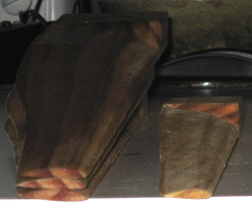
The stepper motors had gotten out of whack and lost steps. After several attempts, and a couple broken bits I was getting frustrated. This had happened from time to time with the smaller blades, but the amount of carving with the larger blades is a multiple of that because not only are they longer, and wider, but I had set the distance of travel down the x-axis to one 32nd of an inch between steps where the airfoil profile was carved to minimize the amount of finish sanding required when done. The straw that broke the camels back for the stepper system was that on one attempt it lost steps on the z-axis, which is the vertical axis, and actually carved the top of the airfoil into the steel surface of the vise I was using to hold the stock material. It carved about a half an inch of it before the end mill snapped.
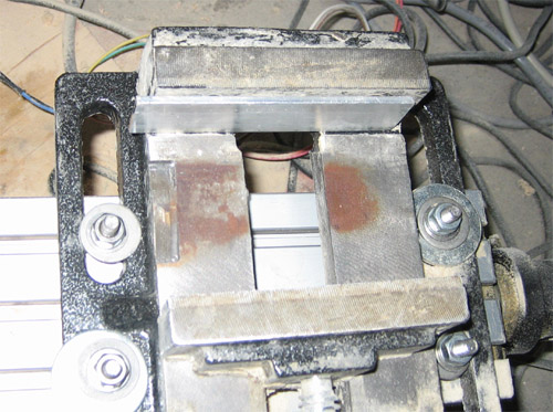
You can see the airfoil caved on the left side of the vise.
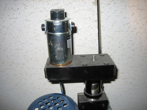
Frustrated, I switched the steppers out for servo motors, which operate with feedback. Now if the milling machine gets out of alignment, the controller receives feedback so it can try to correct the situation, and if it cannot, then it shuts down.
I had one more minor mishap in that I didn't fasten one of the blades securely in the vise, and it slipped while carving. The program ran to the end pushing the blade along, and the only damage to the stock was a slight groove cut at one position out along the blade. I secured the blade and re-ran the program and the blade came out with the only damage shown in the fuzzy pictur below.

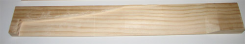
Everything else was uneventful, and I ended up with three blades to test. I gave the blades a quick once over with fine sand paper, and coated them liberally with linseed oil. Here is the front. I put one of the 12 inch blades in there for a size comparison:
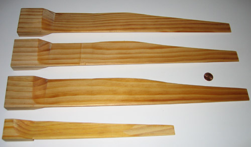
You can see the damage on the middle blade towards the left where it slipped out of the vise.
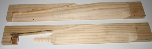
Here is the back:
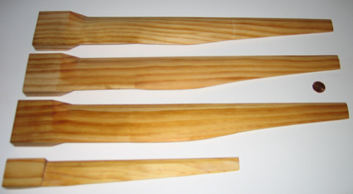
This is a view of the airfoil:
It is interesting to look at the trailing edge of the blade as you can see the theoretical curve and where it gives way to a straight line as the size is limited by the stock of wood used. You can see how the trailing edge of the blade curves up gently from the right side, accelerating as you move towards the left until it abruptly changes to a straight line.

The theoretical chord width from the model I am using doesn't hold up near the root that well anyway as it becomes absurdly large. I maximized the chord and angle for this portion of the blade based upon what the stock would allow.
Next up will be to test these blades out. I purchased a cheap Anemometer set and will have to mount it as well. I plan to use the 30V Ametek motor that DanB graciously gave me when I was out there last April. I don't know how well the power curves of the alternator and the blades will match up, but it is a starting point. I should be able to compare the approximate wind speed with the amps out of the mill to a battery at least. I will have to build a mount and frame for the wind turbine as well. Also, this project is also going to get pre-empted for a bit by an important project to build a pinewood derby racecar in the shape of a shark. :-) I plan to post results as soon as I have them however. Rich Hagen
