Author Topic: Monday Jan 23  (Read 3987 times)

0 Members and 1 Guest are viewing this topic.

DanB

  • Global Moderator
  • SuperHero Member
  • *****
  • Posts: 2151
  • Country: us
    • otherpower.com
Monday Jan 23
« on: January 24, 2006, 01:59:11 AM »


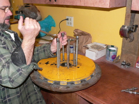
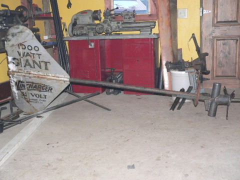
Last week I noticed a weld had broke on my tower, so we brought my 17' machine down on Saturday.

  There were several fatigue cracks and a couple places where pipe had broken.  (scary)

So we fixed the tower...  but the machine also has problems.  The bearing was a touch loose.  The stator had been warped last summer after a lightning strike so the adjustment is very touchy.  So.. It had scraped a bit on the stator.    Most of the magnets in the top rotor had come loose and moved about 3/8" out.  And - it's been making a weird clinking sounds for a while.  In some places the polyester resin had broken up, and become loose between the magnets.  It was clinking every time it went around and rubbing on the stator.


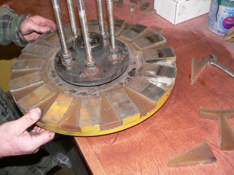
Theres the back magnet rotor/hub.  No damage to the magnets - I'm a bit surprised the plating didn't get damaged.  This is all we did for this machine today, we're waiting on some epoxy to redo the magnet rotors and patch the stator.  I expect it'll be a quick fix.  I'm not that surprised about the bearing ply - but it does confirm my feelings that this hub was on the small side, I expect it'll need adjustment once a year at least.


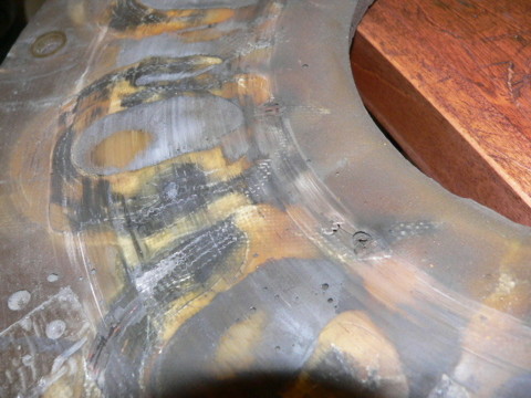
There's a close up on the stator.  It looks somewhat blackened/burned - and it is, it cooked for 10 min after our lightning strike blew our rectifiers in Aug.  Amazingly it still works.


Rich started a new machine today for himself.  This will be an experiment... a single rotor 7' machine.  We're not making the best use of magnets (We never do.. We sell magnets ;~)  )here with one rotor, but the plan/assembly is quick and easy.    Rich is winding coils with 50 turns of #13 gage wire.  I expect this'll be an OK 200-300 watt machine, hopefully it'll be good in low winds.


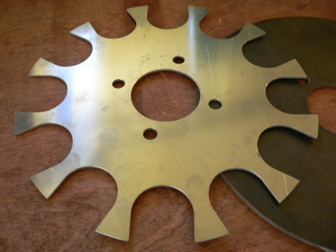
Pictured above is the single blank magnet rotor, and the template for the 2" round x ½" thick magnets we're using.


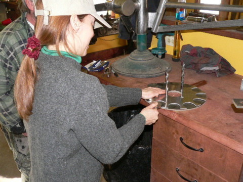
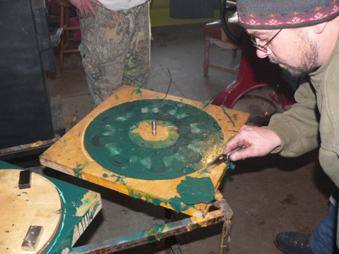
Michelle putting down the magnets...
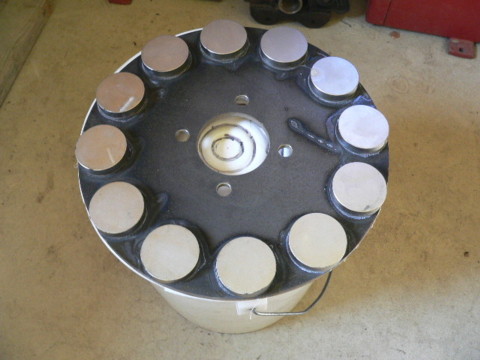


The magnet rotor...


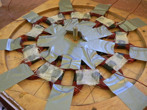
All the coils are hooked up and ready for casting.  This stator is almost identical to the single rotor we made for Dan (I think we used 53 windings in his) and these round magnets perform just about exactly the same as the wedge magnets we used on his.  The round magnets are bigger, and not ideal - but they cost less that wedge shaped magnets.


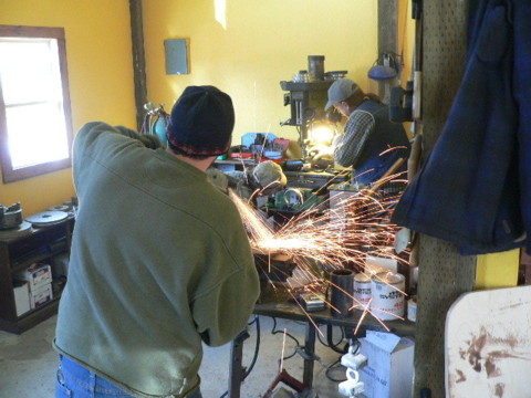
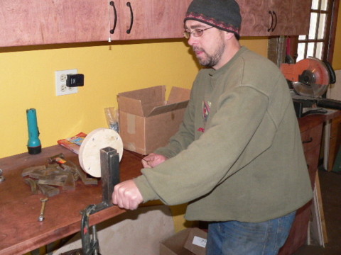
Rich is welding/grinding up the frame for his wind turbine while Scott is working on metal parts for his 11' machine.  (the one we started last week without furling, a 2 bladed 11' win charger prop, a win charger tail and a win charger airbrake.


Scotts alternator will have no offset - its going to stand straight off the yaw bearing.


Scotts machine coming together!


Riches stator came out nicely.


There's how it'll look with the tail.


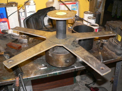
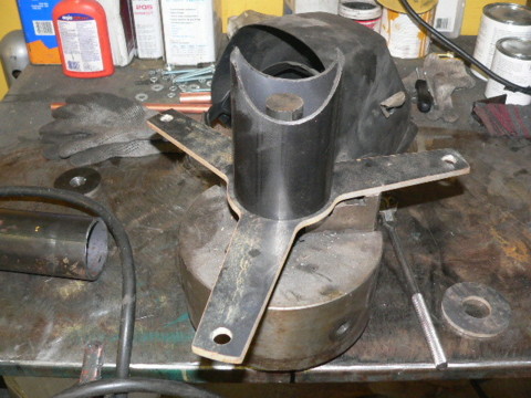
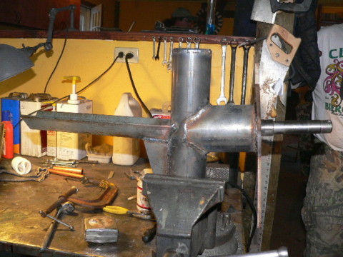
Theres the spindle for my new machine(pointing down in the chuck) and the stator bracket, and the ring that supports it in the back.  The stator bracket is 28" diameter, with 5 spokes cut from 3/8" steel.  We'll use 5/8" stainless all thread on this machine wherever we normally use half inch stuff.


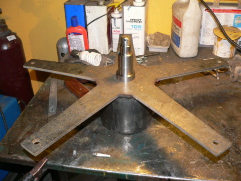
There it is welded together.  We'll not do anymore metal work on this one till the alternator is assembled.  It's already getting heavy.


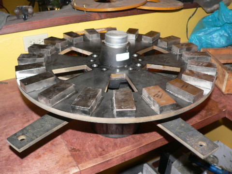
There she is with a magnet rotor on it just for fun.  Fun/busy day.  Nice to get started on my new big machine.  We almost completed Riches machine, we started on it around 11:00 and all that remains is to cut some all thread and assemble it.  (and paint it)

Scott's 11' machine will be a fun experiment.  It was also interesting to see how my 17' machine had some problems.

« Last Edit: January 24, 2006, 01:59:11 AM by (unknown) »
If I ever figure out what's in the box then maybe I can think outside of it.

gator

  • Newbie
  • *
  • Posts: 21
Re: Monday Jan 23
« Reply #1 on: January 23, 2006, 07:28:11 PM »
Speaking to you last week about your 17'machine, I think I'll tone my first one down.  I ordered some of Hugh's books from you and am trying to solidify a tower design.  I'll need to go up about 60' or so.  I was hoping that pipe slid in pipe and welded with 5/16" and 3/8" guy wires would do the trick (wires places every 18ft). I think this is what you recommend but not sure for that height. With your pipe cracking...was it the center beam or the side pieces that broke loose?  I was going to use 3.5", 3" then 2.5" schedule 40 and at the very top a piece of 3" for the yaw bearing.  What do you think?  It's tricky located a good site on top of the hill.  I think I'll have to go down the hill some to avoid trees from guy wire interference (wife won't allow cutting them down).  Would be better anyway to get the lightening rod away from the house somewhat.  Nice work on the big machine.  Would be curious in knowing what my 60 foot tower would hold doing it this way?  Not withstanding tornadoes, we have seen up to 100 mph straight line winds here.
« Last Edit: January 23, 2006, 07:28:11 PM by gator »

Ding123

  • Jr. Member
  • **
  • Posts: 81
Re: Monday Jan 23
« Reply #2 on: January 23, 2006, 07:36:47 PM »
I'm sorry to hear about your mill. but as you know....Mother Nature is a sweetheart.As soon as I saw your pics.I called for the woman. "Come here and look at someone who really knows what they are doing!!!!!DanB" I said and she came runnin!!!

We looked at your pics and read the captions and were amazed at all the work that can be done when you know what you are doing! I told her as soon as I get my hands on some  magnets from you guys,I will be building a real mill just like DanB.

and she said "YEH, RIGHT"!

Ding
« Last Edit: January 23, 2006, 07:36:47 PM by Ding123 »

harrie

  • Sr. Member
  • ****
  • Posts: 365
Re: Monday Jan 23
« Reply #3 on: January 23, 2006, 08:58:50 PM »
Great Dan, I am like the many that really enjoy the mondays with all the pictures. keep up the good work.

Great Fun, harrie
« Last Edit: January 23, 2006, 08:58:50 PM by harrie »

DanB

  • Global Moderator
  • SuperHero Member
  • *****
  • Posts: 2151
  • Country: us
    • otherpower.com
Re: Monday Jan 23
« Reply #4 on: January 23, 2006, 09:44:31 PM »
"Speaking to you last week about your 17'machine, I think I'll tone my first one down."


to be honest I'm surprised I've not had more trouble than I have with this one...


  I ordered some of Hugh's books from you and am trying to solidify a tower design.  I'll need to go up about 60' or so.  I was hoping that pipe slid in pipe and welded with 5/16" and 3/8" guy wires would do the trick (wires places every 18ft)."


Sounds reasonable - 3/8" at the top and 5/16" below that.


 "I think this is what you recommend but not sure for that height. With your pipe cracking...was it the center beam or the side pieces that broke loose?"


No - it was not the main pipe itself, all the little 1" stuff I welded around it to make it more rigid.


 " I was going to use 3.5", 3" then 2.5" schedule 40 and at the very top a piece of 3" for the yaw bearing.  What do you think? "


I think 2.5" sched 40 is OK (but perhaps nominal) for a 10' machine that furls early.  Matt's 15' machine sits on 3" stuff and its definitely nominal (wise to shut down in high winds).  A discussion of all this in more detail would be fun.  Im a bit confused about how to engineer towers from pipe and tubing.  Mick Sagrillo, at the last seminar told me that the strength of the tower is related to the square of the wall thickness, and the 4th power of the diameter.  (so double wall thickness, its 4x stronger - double diameter its 16X stronger).  But other folks have told me that its stronger according to the square of the diameter and at this time Im a bit confused...

Also  remember that not only does the force against the tower increase (with the square of the blade diameter I assume), but at the same time the distance above the top wire increases.


So your tower plan there sounds OK to me for perhaps a 10' machine, I'd not dare stick a 17' machine on it.


 "It's tricky located a good site on top of the hill.  I think I'll have to go down the hill some to avoid trees from guy wire interference (wife won't allow cutting them down).  Would be better anyway to get the lightening rod away from the house somewhat.  Nice work on the big machine.  Would be curious in knowing what my 60 foot tower would hold doing it this way?  Not withstanding tornadoes, we have seen up to 100 mph straight line winds here."


If the machine furls nicely then high winds are not too much problem I don't think - unless they're gusty/violent.

« Last Edit: January 23, 2006, 09:44:31 PM by DanB »
If I ever figure out what's in the box then maybe I can think outside of it.

force9BOAT

  • Full Member
  • ***
  • Posts: 140
Re: Monday Jan 23
« Reply #5 on: January 23, 2006, 10:30:14 PM »
This is the second wind turbine I know of to be damaged by a lightning strike.  I'm wondering if it would make sense to weld a lightning rod to the head assembly.  I suppose the rod would have to be at least as long as the blades.  Maybe the grounding wire could run down the inside of the tower pipes and then buried deep in the ground.  I wonder if that might prevent future lightning damage.  


Rob

« Last Edit: January 23, 2006, 10:30:14 PM by force9BOAT »

ghurd

  • Super Hero Member Plus
  • *******
  • Posts: 8059
Re: Monday Jan 23
« Reply #6 on: January 23, 2006, 11:32:31 PM »
'Back in the day' when I could remember stuff about my bows and appropriate arrows, there was some great info about wall thickness and OD related to strength, etc.

May be worth a Google.


Now I have them make the same as what I had before.  :/

They still work.  :)

G-

« Last Edit: January 23, 2006, 11:32:31 PM by ghurd »
www.ghurd.info<<<-----Information on my Controller

terry5732

  • Sr. Member
  • ****
  • Posts: 283
  • Country: us
Re: Monday Jan 23
« Reply #7 on: January 23, 2006, 11:32:58 PM »
Look into lightning rod principle. You are not trying to attract lightning to the rod but rather disipate the atttraction that the tower builds from being in the wind.

Aren't those coils on the small one a little (lot) misshapen for the round mags?!
« Last Edit: January 23, 2006, 11:32:58 PM by terry5732 »

willib

  • SuperHero Member
  • ******
  • Posts: 2414
  • Country: us
Re: Monday Jan 23
« Reply #8 on: January 24, 2006, 12:21:36 AM »
i was going to say that but...the coils are allready wound , and probably firmly embedded in polyester by now.
« Last Edit: January 24, 2006, 12:21:36 AM by willib »
Carpe Ventum (Seize the Wind)

DanB

  • Global Moderator
  • SuperHero Member
  • *****
  • Posts: 2151
  • Country: us
    • otherpower.com
Re: Monday Jan 23
« Reply #9 on: January 24, 2006, 07:50:49 AM »
Considering the diameter of the magnet rotor, the size of the magnets and how closely the magnet are crowded, I think they're about right....  but I could be wrong!
« Last Edit: January 24, 2006, 07:50:49 AM by DanB »
If I ever figure out what's in the box then maybe I can think outside of it.

DanB

  • Global Moderator
  • SuperHero Member
  • *****
  • Posts: 2151
  • Country: us
    • otherpower.com
Re: Monday Jan 23
« Reply #10 on: January 24, 2006, 07:53:05 AM »
Hi Rob- the machine did not get hit directly, a nearby tree got hit.  It was close enough though to wipe out one of the rectifiers so that current was running back up the line and heating the coils.  We didn't think about it, or notice it untill we saw smoke at the tower top (about 10 min after the strike).
« Last Edit: January 24, 2006, 07:53:05 AM by DanB »
If I ever figure out what's in the box then maybe I can think outside of it.

fishfarm

  • Jr. Member
  • **
  • Posts: 65
Re: Monday Jan 23
« Reply #11 on: January 24, 2006, 09:16:56 AM »
Since rectifiers can fail for reasons other than lightning, perhaps one of our electronics wizards can design a simple reverse current alarm/circuit breaker to prevent continued damage and avoid depleting the battery. Just thinking out loud.
« Last Edit: January 24, 2006, 09:16:56 AM by fishfarm »

terry5732

  • Sr. Member
  • ****
  • Posts: 283
  • Country: us
Re: Monday Jan 23
« Reply #12 on: January 24, 2006, 03:35:47 PM »
That's a strange failure. I would expect a blown rectifier to be an open circuit. Maybe a shortcoming of the preassembled bridge types - where everything is crammed into one package. Mebbe makes individual rectifiers look more appealing.
« Last Edit: January 24, 2006, 03:35:47 PM by terry5732 »

DanB

  • Global Moderator
  • SuperHero Member
  • *****
  • Posts: 2151
  • Country: us
    • otherpower.com
Re: Monday Jan 23
« Reply #13 on: January 24, 2006, 04:02:00 PM »
I've seen quite a few blow up here.  Every time (Except this one time) they've blown such the AC leads were shorted and the wind turbine stopped.  This is the only time I've seen one blow to closed circuit such that it allowed current to flow from the batteries to the wind turbine.
« Last Edit: January 24, 2006, 04:02:00 PM by DanB »
If I ever figure out what's in the box then maybe I can think outside of it.

willib

  • SuperHero Member
  • ******
  • Posts: 2414
  • Country: us
Re: Monday Jan 23
« Reply #14 on: January 24, 2006, 05:03:48 PM »
you musta chose the weegie board method of determining the rotor size.


the rotor should have been 13.825" in dia.

http://www.otherpower.com/images/scimages/2965/9coil12mags2inch.GIF

« Last Edit: January 24, 2006, 05:03:48 PM by willib »
Carpe Ventum (Seize the Wind)

crashk6

  • Jr. Member
  • **
  • Posts: 71
Re: Monday Jan 23
« Reply #15 on: January 24, 2006, 06:30:07 PM »
I think you mean an Ouija board, not being critical I'm just a stickler for details with this sort of thing. Although Ouija is just the trademarked name game company Parker Brothers calls theirs. We don't consider them a toy in my circles. Around here we call ours (not made by Parker brothers and not constructed of cardboard) a spirit board.


This has been your random information for the day, enjoy!

--

crashK6

« Last Edit: January 24, 2006, 06:30:07 PM by crashk6 »

Drives

  • Full Member
  • ***
  • Posts: 101
  • Country: us
Re: Monday Jan 23
« Reply #16 on: January 24, 2006, 06:44:24 PM »
In my experience of working with power electronics, most (99%) semiconductors will fail short circuited first until enough current is forced through the package to cause it to open.  


It is not a guaranteed fix, but cheap lightning protection is to place 6 qty MOV's on your 3 phase rectifiers.  Connected. 3 qty phase to phase, and 3 qty phase to ground.  They should have a voltage rating higher than the voltage you are generating, and as high a joule rating as you can afford.  In a lightning hit they will clamp and try to absorb the surge.  There is no man made device that will prevent damage in case of direct hits, but MOV's will help.


Search this board, and lightning has been addressed many times.  Many people know much more about this subject.


Dan, keep up the good work, I look forward to every Monday!

« Last Edit: January 24, 2006, 06:44:24 PM by Drives »

willib

  • SuperHero Member
  • ******
  • Posts: 2414
  • Country: us
Re: Monday Jan 23
« Reply #17 on: January 24, 2006, 07:32:42 PM »
My apologies , Spirit board then  , actually i had no idea how to spell it , so i typed what i thought it sounded like into google and that popped up.
« Last Edit: January 24, 2006, 07:32:42 PM by willib »
Carpe Ventum (Seize the Wind)

DanB

  • Global Moderator
  • SuperHero Member
  • *****
  • Posts: 2151
  • Country: us
    • otherpower.com
Re: Monday Jan 23
« Reply #18 on: January 24, 2006, 08:35:49 PM »
I used them because that's what we have...

but I would disagree that there's not plenty of room for compromise here.  What you've drawn might slightly make best use of the magnets, but the coils being totally round, and larger are also more resistive.  The edges of round magnets, where they are closest to each other do us very little good I think, we can afford to crowd round magnets together more than we can afford to crowd rectangular, or wedge shaped magnets.  I wasn't really shooting for the most effective thing here - I'm kind of shooting for a quick/simple reletively cheap 7' machine.  I think this alternator will do the trick as long as we furl it early.  (but I could be wrong... usually I find out I was wrong about many things as time passes)
« Last Edit: January 24, 2006, 08:35:49 PM by DanB »
If I ever figure out what's in the box then maybe I can think outside of it.

terry5732

  • Sr. Member
  • ****
  • Posts: 283
  • Country: us
Re: Monday Jan 23
« Reply #19 on: January 24, 2006, 10:05:28 PM »
As the magnet passes you should get an output from the leading edge, as it progresses you will have the two halves of coil making opposing current (heat - no output) , then an output as it leaves. The center of the coil pretty much has to be the size of the magnetic field of the magnet. You may be compressing the field by close spacing, but I don't think you will be making it smaller than the magnet.
« Last Edit: January 24, 2006, 10:05:28 PM by terry5732 »

DanB

  • Global Moderator
  • SuperHero Member
  • *****
  • Posts: 2151
  • Country: us
    • otherpower.com
Re: Monday Jan 23
« Reply #20 on: January 24, 2006, 10:14:52 PM »
"As the magnet passes you should get an output from the leading edge, as it progresses you will have the two halves of coil making opposing current (heat - no output) ,"


Perhaps I have a misconception here... but I think I disagree.  I agree about the 'no output' at that moment, but I don't think we're generating heat.  I think no current flows at all...  am I wrong in this?  I've looked at this sort of thing on a scope (just the output of the phase itself) and I can see the flat spot (where we have some cancellation) but I don't grasp how we'd be generating heat in the coil there.

« Last Edit: January 24, 2006, 10:14:52 PM by DanB »
If I ever figure out what's in the box then maybe I can think outside of it.

willib

  • SuperHero Member
  • ******
  • Posts: 2414
  • Country: us
Re: Monday Jan 23
« Reply #21 on: January 24, 2006, 10:38:22 PM »
what are the dimentions of your coils?

what is rotor the size ?
« Last Edit: January 24, 2006, 10:38:22 PM by willib »
Carpe Ventum (Seize the Wind)

DanB

  • Global Moderator
  • SuperHero Member
  • *****
  • Posts: 2151
  • Country: us
    • otherpower.com
Re: Monday Jan 23
« Reply #22 on: January 24, 2006, 10:42:35 PM »
The rotor is 12" diameter.

the coils are such that 9 fit pretty much perfectly around the rotor when the holes in the coils are centered over the magnets.  The holes in the coils are just about 1" wide (slightly less at the bottom).  And the holes are just under 2" tall.
« Last Edit: January 24, 2006, 10:42:35 PM by DanB »
If I ever figure out what's in the box then maybe I can think outside of it.

willib

  • SuperHero Member
  • ******
  • Posts: 2414
  • Country: us
Re: Monday Jan 23
« Reply #23 on: January 24, 2006, 11:49:10 PM »
So your coil legs are just under 3/4" wide.

I dont know what to tell ya about the heating question. because mine dont have have  a dead spot.

just perfect looking sine waves .


no not bragging , well maybe a little ..

http://www.otherpower.com/images/scimages/2965/sine_wave.JPG

« Last Edit: January 24, 2006, 11:49:10 PM by willib »
Carpe Ventum (Seize the Wind)

jlt

  • Sr. Member
  • ****
  • Posts: 368
Re: Monday Jan 23
« Reply #24 on: January 25, 2006, 06:01:10 AM »
just my two cents about using fiber glass resin.In using it with out any glass fiber in it. it is very brittle. and has very little strengh.you might try to add a few glass fibers when you cast your roters. maybe you could cut some up with a paper cutter .or just use some sizzers. use half inch long fibers just a few and it wont be breaking apart so easy.I have also used a product called tiger hair.add some to your resin mix and it will be a lot stronger.keep up the great work that you are doing.hope to see the big monster up pretty soon
« Last Edit: January 25, 2006, 06:01:10 AM by jlt »

DanB

  • Global Moderator
  • SuperHero Member
  • *****
  • Posts: 2151
  • Country: us
    • otherpower.com
Re: Monday Jan 23
« Reply #25 on: January 25, 2006, 07:43:19 AM »
You'd probably be surprised how this would show a nearly perfect sine wave as well.  But - when we're charging batteries a perfect sine wave isn't important, so long as Im not generating heat in the coil.  
« Last Edit: January 25, 2006, 07:43:19 AM by DanB »
If I ever figure out what's in the box then maybe I can think outside of it.

elvin1949

  • Hero Member
  • *****
  • Posts: 645
Re: Monday Jan 23
« Reply #26 on: January 25, 2006, 07:44:40 PM »
Dan

Being wrong sometime's is good.

 It is how we learn,and it is fun.

later

Elvin
« Last Edit: January 25, 2006, 07:44:40 PM by elvin1949 »