Author Topic: turbine /RE system automation  (Read 2711 times)

0 Members and 1 Guest are viewing this topic.

electronbaby

  • Sr. Member
  • ****
  • Posts: 407
  • Country: us
    • Windsine.org
turbine /RE system automation
« on: March 26, 2006, 07:29:01 PM »


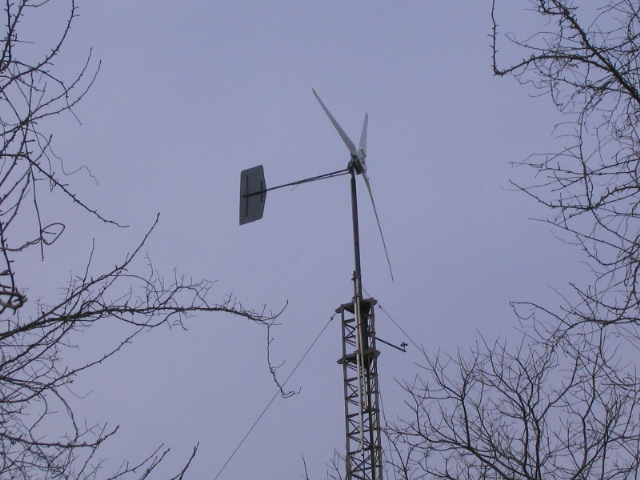
Here is my 16' dual rotor. after a stator melt down caused by a nor-easter last fall, everythings been fine. I made 2 more direct replacements for the stator and i hope to run this machine for a while.. i have not had that much time to play lately  :-/  I have to spent the rest of this year getting the new shop going. anyway, which brings me to this post. I have been playing around with this idea for a while and now that i have everything built up, it seems to work pretty well. I didnt like the idea of dump loads because i was always striving to keep my batteries at their float voltage and this is alot "easier" on them. It seems they take less abuse this way. I also have a complete pentametric system set up and i have to watch the amp hour totals and the efficiency factors to see if this has less of a negative impact on them, or if it will make any difference at all. I cant say this is the best way to control the turbine, but it makes it so that it only really turns on when it needs to. I have alot of solar (1.5kW) and this supplies the house and charges the batts during the day.


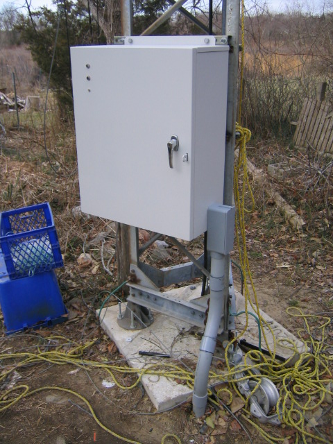
This is a weatherproof steel NEMA box that i have attached to the wind tower out back. It is connected to the house  by a 2" underground PVC conduit. This conduit carries three 2AWG welding cables for the turbine power output which runs to the rectifier. Also in this conduit is the multi conductor control cables, one of which, is used for this automation system. You can see the panel mounted LED's that are tied into the limit switches of the actuator so i can get a visual confirmation of the position of the switch. I have these postioned so i can see them from the house.


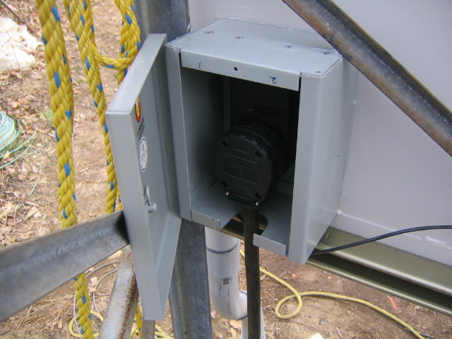
Im just as guilty as everyone else lol, I think it IS a better idea not to have slip rings lol. Its not very turbulent in my area, so it seems to work out well. Its easier this way. Anyway, this is the plug box that attaches to the back of the NEMA box and protrudes into the inside of the tower. It holds the outlet recepticle that the large 3 pronged plug plugs into. the cover can be secured, preventing anyone from pulling the plug out.


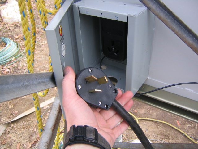
Here is the plug. The excess cord dangles inside the tower legs and when it gets twisted, the plug can be unplugged and unraveled, and plugged back in. Pretty easy, works well. I would have used a twist-lock type plug, but i  had trouble finding one which had an equivalent 50A rating. so i used this type, not a big deal.


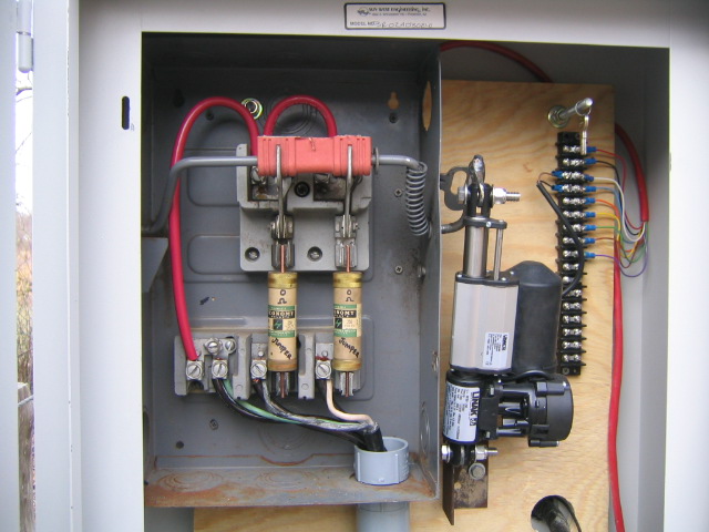
Here is the view inside of the NEMA box. You can see the type of knife disconnect switch i used. I would have loved to use a 3 pole switch, but i didnt have one laying around. I think this works just as well, you can see, i bridged the 1st phase across the top two fingers. and the other 2 phases to the lower half of each knife. When the actuator engages the switch in the up postition, all 3 phases are effectively shorted out. The things that look like fuses, are not really fuses. they are jumpers. I took them apart and took out the fuse elements. I then used 4awg wire to bridge them, so they effectively became jumpers. It was easier than finding a way to connect the cable dirrectly to the lower fingers.

You can see the control cable and how it breaks out to the terminal strip. eventually the other wires will carry a constant 24vdc, the anemometer signal which is then supplied to a comparator. This will determine, by judging wind speed, if the turbine will come on or not. This will help protect it and will shut it down in a high, sustained wind condition. A little safer. I dont have to stress at night if the wind picks up lol (thats how i blew up the first stator).

The actuator is made by LINAK Corp. It seems to be very well made and i think it was NOS. I had gotten it off of ebay for around $50 if i recall. Although the speed is a little slow for this application, the torque is of no concern because it claims to have 400lb. of lift lol  whatever, it works well.


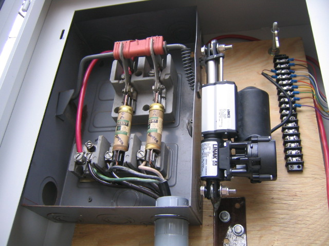
Another shot of inside the tower box.


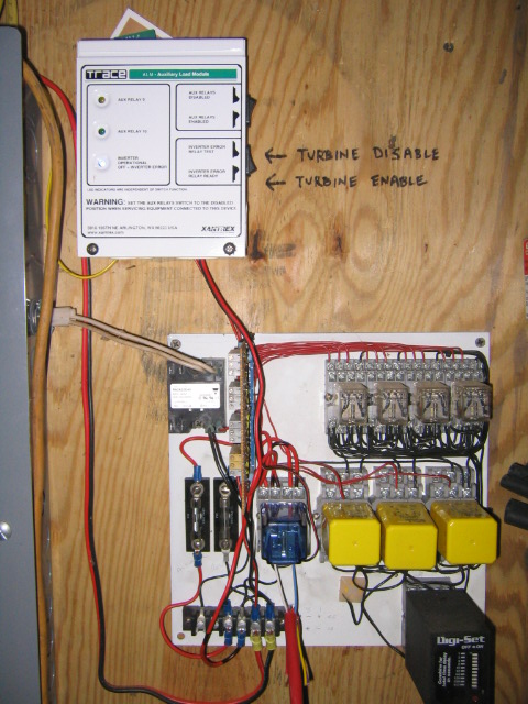
Here you can see the ALM control module, that i use with my SW PLUS 4024 inverter. I have the voltage thresholds set to turn on RELAY 10 (turbine activation relay) at 24.5vdc and to turn it off at 26.5vdc.

This allows it really, only to run when its needed, because the batt voltage rarely ever goes that low... the solar keeps it up. This relay is also tied into the temp compensation part of the inverter. Relay 8 is the relay that controls the dump load circuit (110vac through the breaker panel). This is still active when i decide if i want to plug in a dump load such as a oil filled radiator heaters in the winter, or air conditioners in the summer. I tend to not use this dump load circuit as much as i used to, and with the automation relay, the turbine simply does not have to come on at all as long as the battery voltage is kept up.

Another neat feature that i incorporated, was the use of RELAY 11 (error relay). Under normal circumstances, this relay is energized. If at any time, there is a problem with the inverter, or it reaches an error state (over voltage, over temp, etc.) the error relay de-energizes. Also, if at any time the control voltage is lost to the secondary relay panel, the turbine control relay drops (blue relay - its wired for reverse logic) and the turbine will shut down. The control signal from Relay 10 is in series with Relay 11 so if there is an error state, the turbine is shut down automatically also. This is more like a safety feature, and i sleep a little easier.


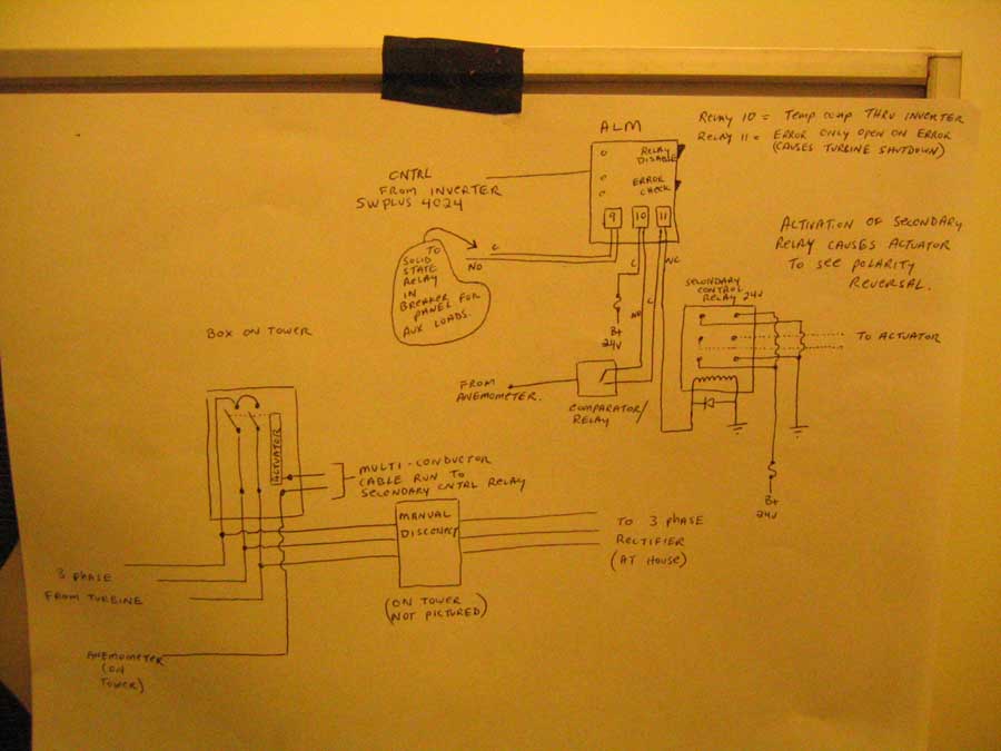
Here is the schematic of the automation system. you can see how it utilizes the ALM to control the turbine and the anemometer to sense wind speed. I want to eventually use some type of programmable micro controller to take the place of the comparator and it would be nice to have manual control of the turbine through the touch screen terminal i use to run the pentametric communication software.

By the way, there is a write up on the pentametric system in the latest issue of Homepower magazine if anyone is interested. :-)


Overall, this seems to be working out good for me. Although I always should keep a close eye on the system as it grows, I seem to be increasingly busy lately and its nice to not have to worry about the turbine smoking another stator, or having to manually shut it down every time there is a storm. Time will tell though. just figured id share it.  :-)


Have Fun,

RoyR

KB2UHF

« Last Edit: March 26, 2006, 07:29:01 PM by (unknown) »
Have Fun!!!  RoyR KB2UHF

Ding123

  • Jr. Member
  • **
  • Posts: 81
Re: turbine /RE system automation
« Reply #1 on: March 26, 2006, 07:05:45 PM »
Electronbaby,our computer was down for a while, I'm trying to catch up on all the stuff I missed and boy ,did I miss alot!!!That is just about the smartest machine I have seen yet! I was wondering if you could tell a fella or ,as far as that goes,a whole bunch of fellas....where you get those relays. It would make it easier for the little woman as , it would save her a few trips to the mill, turning things on and off.....her fingernails are just about gone!LOL!!!!

« Last Edit: March 26, 2006, 07:05:45 PM by Ding123 »

harrie

  • Sr. Member
  • ****
  • Posts: 365
Re: turbine /RE system automation
« Reply #2 on: March 26, 2006, 08:25:27 PM »
Hi Roy. Very impressive set up there, I wish I had the ability to do all that, I have no trouble with the mechanical building, and basic electronics, but would probely have to purchase a ready made set up like that. looks very neat, and would give a guy ease of mind with our weather changes.
« Last Edit: March 26, 2006, 08:25:27 PM by harrie »

SparWeb

  • Global Moderator
  • Super Hero Member Plus
  • *****
  • Posts: 5452
  • Country: ca
    • Wind Turbine Project Field Notes
Re: turbine /RE system automation
« Reply #3 on: March 26, 2006, 09:43:32 PM »
Roy, that's a great set-up.  I saw the knife switch and I thought of Dr. Frankenstein, screaming "It's alive!". :))

Thanks for sharing; we all benefit from the sum of the ideas that show up here.

« Last Edit: March 26, 2006, 09:43:32 PM by SparWeb »
No one believes the theory except the one who developed it. Everyone believes the experiment except the one who ran it.
System spec: 135w BP multicrystalline panels, Xantrex C40, DIY 10ft (3m) diameter wind turbine, Tri-Star TS60, 800AH x 24V AGM Battery, Xantrex SW4024
www.sparweb.ca

electronbaby

  • Sr. Member
  • ****
  • Posts: 407
  • Country: us
    • Windsine.org
Re: turbine /RE system automation
« Reply #4 on: March 27, 2006, 06:02:47 AM »
Ding123, the relays are nothing fancy. Just 24vdc coils, standard DPST relay. Its wired so that the actuator connects to the common on the relay. The 24vdc +- connect to one side and the -+ connect to the other side of the relay. when the relay is energized, its causes a simple polarity reversal and the actuator goes in and out respectively. once the limit switches on the actuator are reached it stops, and awaits the next polarity reversal to reverse it. Pretty simple, but works well.


Im glad you like it.  :-)

« Last Edit: March 27, 2006, 06:02:47 AM by electronbaby »
Have Fun!!!  RoyR KB2UHF

electronbaby

  • Sr. Member
  • ****
  • Posts: 407
  • Country: us
    • Windsine.org
Re: turbine /RE system automation
« Reply #5 on: March 27, 2006, 06:04:55 AM »
Im not sure anyone manufacturer makes anything like this for small scale wind setups. I know bergey makes a control for their XL1 turbine, but i think it uses a dump load. It might give you the option to shut it down remotely, not sure though...


RoyR

« Last Edit: March 27, 2006, 06:04:55 AM by electronbaby »
Have Fun!!!  RoyR KB2UHF

BT Humble

  • Sr. Member
  • ****
  • Posts: 475
Re: turbine /RE system automation
« Reply #6 on: March 28, 2006, 03:14:01 PM »
That's a pretty good idea.  For the Fiji setup I just used a 3-way ganged switch/circuit breaker for the windmill shutdown.  The 3-phase comes in from below, and is split from there to the rectifiers (via the 3 green wires).  The upper connectors of the switch are ganged together with a slab of copper, so when you switch it on it shorts the phases together.


Since this is only a 2.1m/200W mill and the cable run is only 30m, I didn't need to put the shutdown switch right at the tower base.


BTH

« Last Edit: March 28, 2006, 03:14:01 PM by BT Humble »

Frank06

  • Newbie
  • *
  • Posts: 24
Re: turbine /RE system automation
« Reply #7 on: March 30, 2006, 06:54:08 AM »
That's an interesting way to control your machine (well designed and built BTW).  Personally, I wouldn't do it as I think the actuator is more likely to fail (mechanical failure) than the more passive water heater system (resistance heater and PWM control), plus you're not taking advantage of available energy.


You could always use this as a "safety" if you decide to use diversion control.  Diversion would also allow you to use excess PV energy.


Still a very creative system though!

« Last Edit: March 30, 2006, 06:54:08 AM by Frank06 »

electronbaby

  • Sr. Member
  • ****
  • Posts: 407
  • Country: us
    • Windsine.org
Re: turbine /RE system automation
« Reply #8 on: March 30, 2006, 09:17:24 AM »
i agree, mechanical failure was part of my thinking. As i stated in the last paragraph of the posting, there still is a diversion load being used. This way, though, it doesnt need to come on as much. Most of the time, the turbine is in the shutdown position. If something happened to fail, it would be shut down at that point in time, but nothing is certain. Like i said in the post, this type of system is not for everyone, just what works for me. I have been thinking also of a way to do it with some types of solid state devices, but there is nothing that makes you feel better than a hard mechanical closure. Electronic solid state devices could fail or be burnt up at any time, plus you have additive gate currents if you were to use FETs or something equivalent. This mechanical system, in the on state, or off state, draws zero power to maintain a connection. That was important in my design.

But yes, the actuator might / could fail.


this is the kind of constructive criticism i was looking for lol. kinda surprised more people didnt respond :-P


have fun,

RoyR

KB2UHF

« Last Edit: March 30, 2006, 09:17:24 AM by electronbaby »
Have Fun!!!  RoyR KB2UHF

electronbaby

  • Sr. Member
  • ****
  • Posts: 407
  • Country: us
    • Windsine.org
Re: turbine /RE system automation
« Reply #9 on: March 30, 2006, 09:24:58 AM »
Sorry to have missed one of your points Frank. This is at my off grid home. Best use of my solar modules as far as efficiency would be concerned, would be to grid tie. I have not done that. My batteries are usually charged by 9:30 or 10:00 AM and after that the charge controllers shut down. all the loads in the house after that period, until sundown come off the PV array. During the day, i have an excess of power. There is no need to run the turbine when there is an excess, unless possibly to heat water, which you suggested, and believe me, i have given this some thought. possibly in the future, but most of that power would come from the PV array anyway during the day.  The turbine in this sense is more of a back-up.  :-)


RoyR

« Last Edit: March 30, 2006, 09:24:58 AM by electronbaby »
Have Fun!!!  RoyR KB2UHF

cjbotkin

  • Newbie
  • *
  • Posts: 6
Re: turbine /RE system automation
« Reply #10 on: April 04, 2006, 09:54:00 PM »
Hello electronbaby (KB2UHF):  I should have known a great UHF'r was behind such a great automated control panel.  Great stuff.

One question (for now).  Can you please describe more about your "anemometer to comparator" circuit... that "drives" the relays to begin this process?  Is your anemometer simple magnets... linked to an op amp ?  or something else.?


This is really nice and can save us in overspeed situations... Thanks.

Cjbotkin, K0RTM

« Last Edit: April 04, 2006, 09:54:00 PM by cjbotkin »

electronbaby

  • Sr. Member
  • ****
  • Posts: 407
  • Country: us
    • Windsine.org
Re: turbine /RE system automation
« Reply #11 on: April 07, 2006, 07:19:12 AM »
the comparator circuit uses a standard LM319 dual comparator chip. Vcc is through a LM7812 since im using a 24vdc supply, although i think the chip can take up to 36vdc, i just didnt want to chance it.  The anemometer im using puts out AC and is rectified with a half wave bridge. The average voltage output of the anemometer is quite low @ 1v at around 15MPH wind speed. The voltage setpoint for the comparator is set with a pot tapped off a simple voltage divider circuit. The output of the LM319 is tied to a 7404 inverter chip. This is because the output current of the comparator is quite low @ 25mA, so to raise this current handling enough to drive a 5v primary relay, the inverter is used... its just what i had laying around, and i could have done this a million ways. It also gives me the option to reverse the logic of the relay if i want (use two inverters,  the chip holds four).


I kinda want to redo this whole thing with a microcontroller. It seems easier to play around with and possibly more accurate. It seems to work ok. Ive never really seen it shut down yet because of high wind, so time will tell.  :-)


This anemometer circuit only controls the turbine when there is a high wind condition. All the other controlling of the turbine is done with the Trace inverter using the internal programmable voltage setpoints and the ALM module. While under normal operation, a high windspeed condition is reached, the anemometer control will overide the ALM and cause a temporary shutdown for protection.

During shut down, the turbine will still furl, protecting the tower.


Redundancy is key.  :-)

« Last Edit: April 07, 2006, 07:19:12 AM by electronbaby »
Have Fun!!!  RoyR KB2UHF

cjbotkin

  • Newbie
  • *
  • Posts: 6
Re: turbine /RE system automation
« Reply #12 on: April 16, 2006, 10:02:24 PM »
RoyR.


Wow... great details... Thanks for sharing this. :) There is a reason that I haven't put this together yet.  The electronic details.  I just don't have it.  Like many, I've put together numerous kits ... and built some really nice trial n' error circuits... but, I'm not an engineer.  


What anemo are you using to trigger this circuit?


I'm toying with how to do this.  Two thoughts... both based on a particular  anemometer "output" or design.  


(1) Using a Anemometer kit with magnet switch.  (? any anemometer kit ?)


Instructions and ideas on using the "switch / magnet" output...


? - what simple comparator or other circuit would result in a high-wind shut-off?


(2) Using a Hunter (lawn irrigation) anemometer --- designed to trigger a 24vdc relay -- shutoff for sprinklers at 35 mph and back "on" at a lower setpoint.  I think there might be a relay already in this unit... However, I need to get one to see.


? - Not sure yet how to use this to trigger an aux relay for a high-wind shut-off of an axial flux.


Any thoughts are much appreciated.  What anemometer "kit" is your setup based on ?

Thanks,

Cjbotkin

« Last Edit: April 16, 2006, 10:02:24 PM by cjbotkin »

Madscientist267

  • Hero Member
  • *****
  • Posts: 1181
  • Country: us
  • Uh oh. Now what have I done?
Re: turbine /RE system automation
« Reply #13 on: March 20, 2009, 10:25:13 PM »
this is the kind of constructive criticism i was looking for lol. kinda surprised more people didnt respond :-P


Kinda hard to argue something that works... :)


It's an impressive design; there's something to be said about good old fashoned switches... While potentially prone to mechanical problems, the 'look-and-see' troubleshooting that it utilizes can be much easier to deal with than semiconductor. Granted, while you can look and see where the magic smoke leak is, more often than not, it has manifested as a symptom rather than a cause. B-}


Good work dude, keep us up to date on how it performs.


Steve

« Last Edit: March 20, 2009, 10:25:13 PM by Madscientist267 »
The size of the project matters not.
How much magic smoke it contains does !