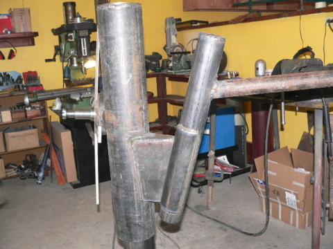
We built the tail bearing for the big machine. It's 22" long made from 2.5" sched 40 pipe which slips over 2" pipe. The tail boom is from 1.5" sched. 40 pipe and it's 10' long. I was unable to finish the tail boom due to lack of materials -but next week all the metal work should be done.
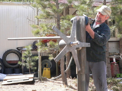
George cleaned up all the welds. The orbital sander does a nice job of finishing the metal/preparing it for paint.
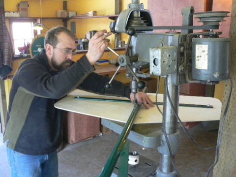
Rich is using the drill press to fit the tail to an 11' machine we built recently.
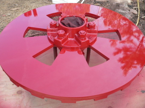
I painted the magnet rotors red for the 20' machine.
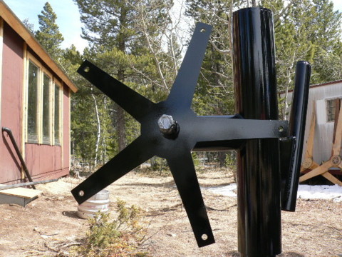
The rest of the machine is black. Next week hopefully I can paint the tail boom and start working on the blade hubs.
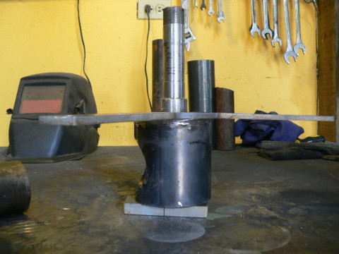
A couple months ago I posted in some detail how we build the assembly pictured above which supports the alternator for a 10' diameter wind turbine. There are lots of different ways to do this stufff... this is just how we do it! Click Here to see that story. Following is how we build the rest of the machine (Except the tail). Normally we use a jig we made up which makes it very fast/easy - but we built one without the jig yesterday just for some pictures. In the picture above we have the assembly that contains the stator brackets/spindle on the steel workbench with a 1/2" thick shim beneath it.
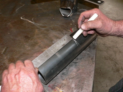
The yaw bearing is a 12" long piece of 2.5" dia sched 40 pipe. We mark the center so that the alternator will be centered on it.
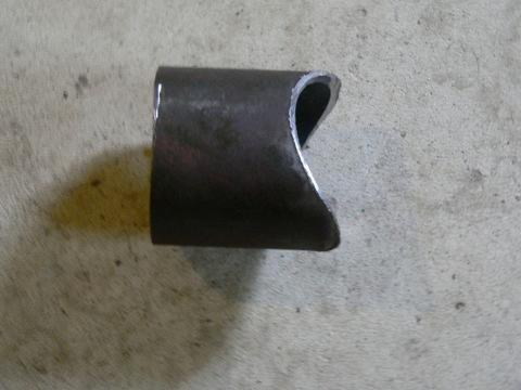
This is the piece that attaches the alternator to the yaw bearing. It's 2" diameter sched 40 pipe, and its 2.5" long at the longest part. We coped it with a hole saw.
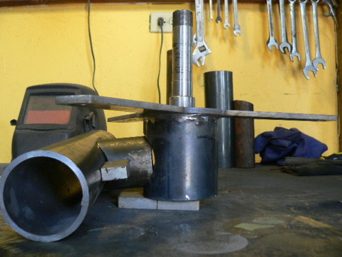
Looking at if from the bottom of the wind turbine: The 2" pipe connects the alternator frame to the yaw bearing as shown above. There should be 5" between the center of the yaw bearing and the center of the spindle (this is the offset that allows the machine to furl).
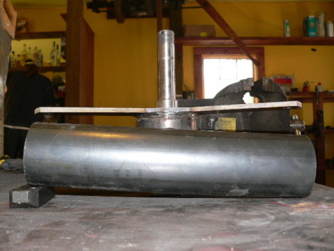
Looking from the side, you can see we've put a shim under the top of the yaw bearing. This makes it such that once welded together, the spindle will tip up about 5 deg to help keep the blade tips away from the tower.
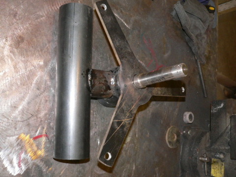
Then we tack weld it all together and double check that everything looks good before doing the final welding.
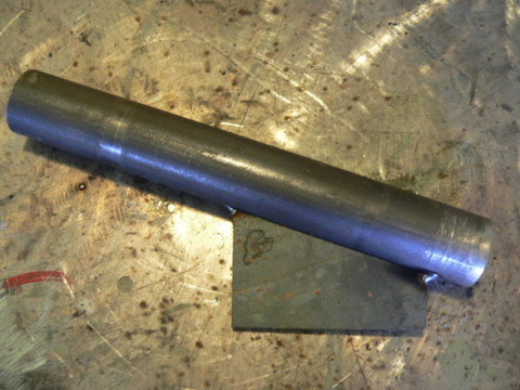
Next we tack weld the tail bracket to the tail pivot. The bracket cut from 1/4" steel. It's 3" tall, 1" wide at the bottom, and 2.125" wide at the top (which makes for an angle of about 20 deg). The tail pivot is 9" long and the top of the tail bracket is located at the center of the tail pivot (so there's 4.5" of pipe above the top of the tail pivot). We position the bracket on the pipe and lightly tack weld it at the top, bottom -and on the center of each side. If we weld too heavily before taking it into position it will pull the bracket to one side as the weld cools - so tack welding first is important.
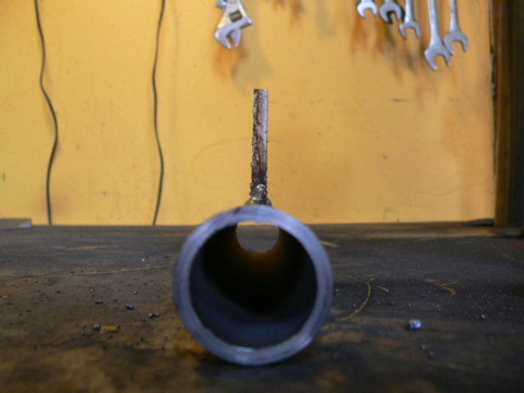
The bracket should be centered on the pipe as shown above.
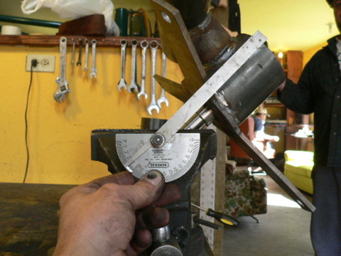
We put the machine in the vice at 45 deg.
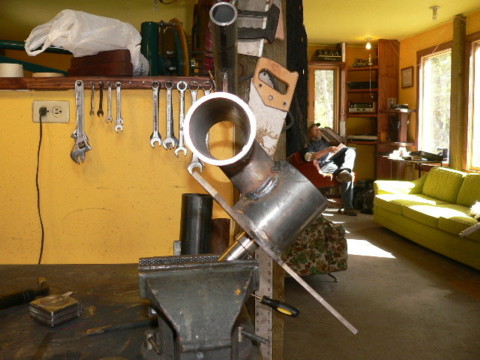
Then tack weld the tail bracket/pivot to the machine so that it points straight up as shown in the picture.
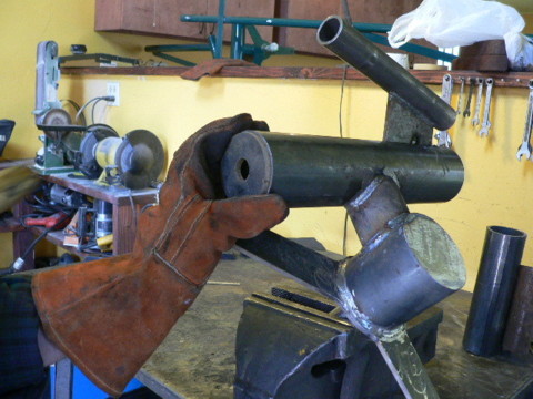
The top of the yaw bearing is a disk about 2.75" in diameter. (its a touch smaller - it's actually a scrap out of the center of a magnet rotor). We drill a .75" hole in it so that the cord can run down through it -and through the tower. The next step is to weld this on.
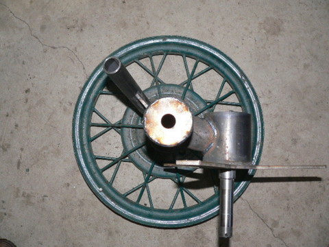
A veiw from the top of the finished assembly. All thats left now for metal work is to build the tail.
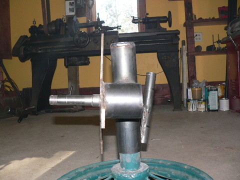
A veiw of the same thing from the side. We never finished the tail on Monday so perhaps next Monday I'll ramble on about that some.
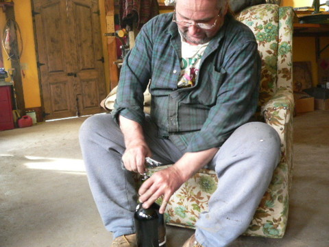
On the lighter side... again - this week, George had problems with the cork screw and spent about 5 min trying not to drop the cork in the bottle!
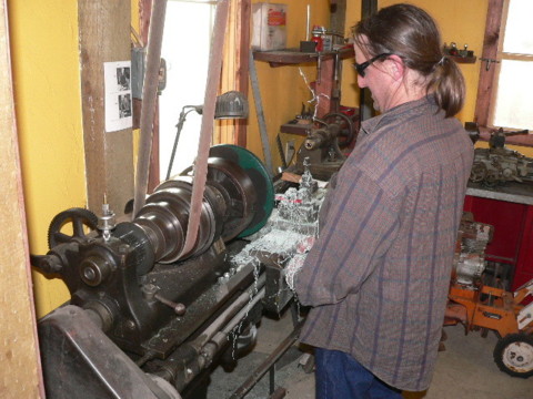
Scott turned the magnet rotors for his new machine. I think maybe next Monday we might get that assembled. It will be fun to see how it works out with a two bladed prop and an airbrake.

Georges supper consists of: Pizza, Beans - ground 'mountain lion' (we all had mountain lion burgers for lunch which was interesting and tasty), and 'red beer' (PBR and spicy V-8).
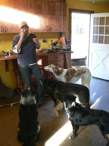
Tom had an audiance while he ate...