It has some old and new ideas incorporated into it's unique design.
I'm not too good at 'splain' things, but here goes...
Double 12" rotors with 24 magnets each, 18 coils on each side of a magnet steel laminated stator. 8 foot prop.
I told you it was different!
This unit was built in an attempt to accomplish several things:
- have fun!
- user adjustable furl
- deal with excessive heat in the stator
- 24 and 48 volt capabilities, maybe higher too
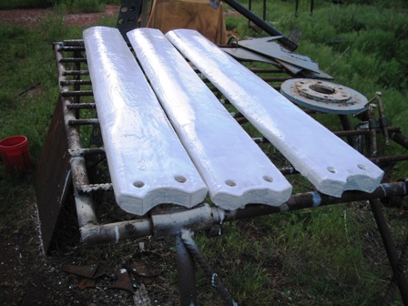
- seal the blades to keep moisture from entering and unbalancing them.
- have fun!
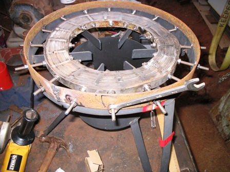
I started off with a piece of 3/4" steel laminate, wound just
like the stators were made on the old otherpower board. I used
the same mold as the rotor was cast in and wound the laminates
as tight as I could. Next, it was drenched in electrical
varnish and air dried. I quickly learned the magnets would
still warp the laminates. So,I drilled 18 holes around the
parameter and inserted 1/4" stainless steel allthread. 3/32"
steel hoops were added to secure the laminated firmly. I also had to weld the laminates about 1/8" deep on each side using a 308 stainless steel rod. The 1/4" allthread was tightned evenly around the hoop with a torque wrench at 12 ft/lbs.
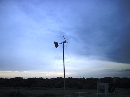
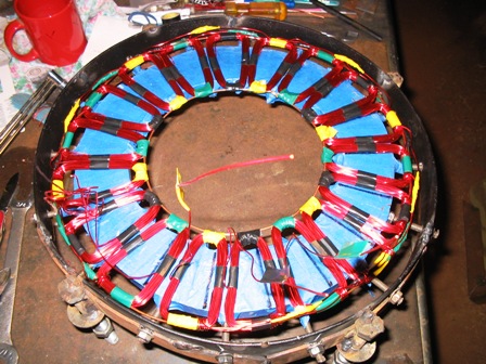
The coils came next. The laminates were covered in painter's tape to avoid any sharp edges coming in contact with the magnet wire. 30 winds each, #18 magnet wire, 18 coils on each side. The legs of each stator were taped together, then the stators were tied with string to keep them on the laminates and in the right place. Varnish was painted on the coils, string and connections. Smooth-on 300 plastic was painted on both stators to seal and 'glue' the coils on the lams. Both stators were wired seperately in star. 12 wires come out of the completed unit and are tied together at the terminal block. The box that houses the terminal block can be seen in the first pic, just behind the stator. Each stator produces about 30 volts when spun by hand. In the near future, MPPT may play a big role in this unit.
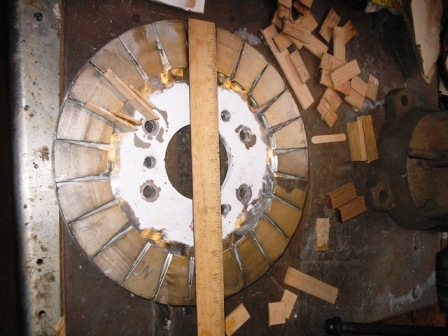
I used a 12" diameter piece of 1/2" steel for the rotors and mounted 24 magnets on each one. Magnets are the 3/32" thick magnets from Windstuff Ed. The edges of the magnets do touch at the edge of the rotor. I think it's probably causing some power
loss. All of this has it's trade-offs. I sealed the entire rotor in Smooth-on 300 and painted them.
Blades are from my original unit. Water was entering the wood where the blades were bolted to the rotor. I drilled out the holes by an inch, poured the Smooth-on into the holes and redrilled them to 1/2". Maybe this will work.
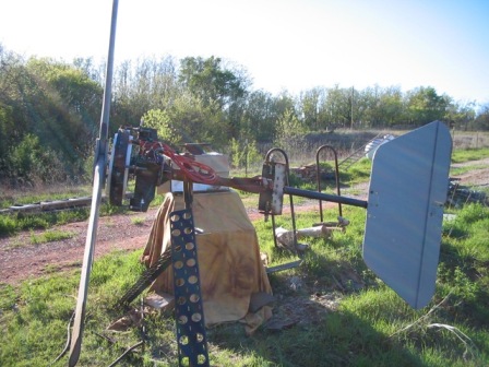
Here's the adjustable furl mechanism.
I've taken the compound hinge assembly and split it up into two angles. The first one that's attached to the yaw bearing pipe is welded in at 10 degrees. The second angle is adjustable to whatever you want. It's a pipe within a pipe, secured by
tightning 4 top bolts. If the bolts fail, the tail should drop and cause the genny to turn backwards and slow down. Out of balance blades should also cause tail drop.
Adjust the angle of the tail and tighten the 4 bolts on the top to control the furl. I used DanB's method using a rope and fish scale to adjust the furl. It's set at 10 pounds.The generator bolts to the flange on the left.
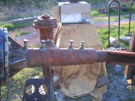
Moch-up of unfinished generator
I've seen 60 volts going into the batteries and 70 Hz when configured for a 48 volts system. The Hz are high enough, it may get a transformer hooked to it, just for fun. As yet,I don't have good solid data on it's output. I plan to hook up my
datalogger to it soon!
Constructive comments are welcome!
