Author Topic: Motor conversion  (Read 4985 times)

0 Members and 1 Guest are viewing this topic.

Jimmy D

  • Newbie
  • *
  • Posts: 29
Motor conversion
« on: March 22, 2008, 05:31:38 PM »
Hello all,

 In 2006 I posted asking if this was a suitable motor: 600v, 3 phase, 1 hp and 8 poles. Zubbly responded that this was an excellent candidate. He recommended cutting down the rotor to accept 1" x 1/4" neo discs, picking the star connection apart and bringing the leads out of the case and reporting back to him for testing procedures. Deep sympatahy to his family:(


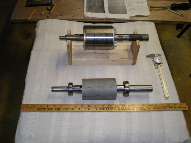
 Here is the original rotor and the new one my son machined for me with the face sandblasted for adhesion of glue and magnets.


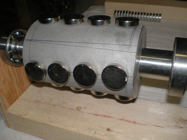
 Here are all my north poles glued in. This isn't easy because although they stick just fine dry, as soon as you apply glue they will repel each other. Skate about.


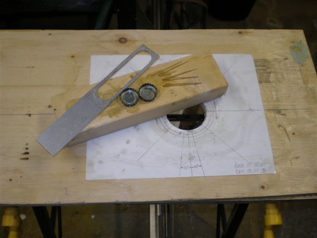
 This is a little tool I made up to corral/control this movement. Also note these small mixing containers you might have lying around are great for small batches of glue.


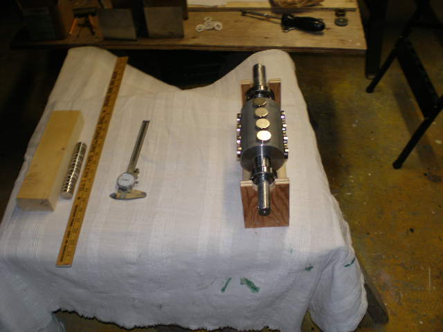
 One row per night was all I could manage.


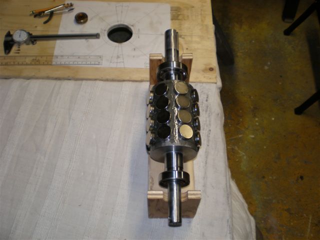
 I thought the south rows would now be a nightmare but I guess flux from the Norths made it easy. Although the allignment tool was still required all four poles were completed in one night. I've refered to glue above, actually this was vinyl ester resin.


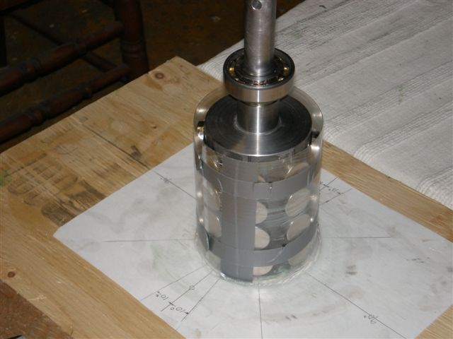
 With a split soda bottle to control circumference, some duct tape, a little car wax and silicone, the form was ready.


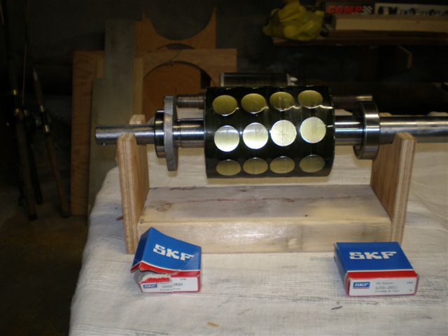
 And there it is with new SKF's ready to roll.


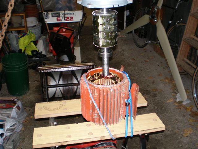
 You guys scared me so badly I wouldn't try this insertion without my chainfall and some sandbags below. Thanks, it went smoothly despite great attractions.


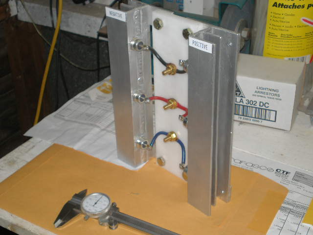
 Thanks to this site and especially to Harry & Nando(where are you guys?) I put together this rectifier. Studs are 90 amp each, from India.


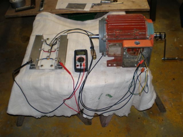
 Now I get into some troubles, the mechanical I can work out however I have very little testing knowledge. Hand cranking in delta at 150 rpm open I see 70vdc. When hooked to a baby 48v bank I see 60vdc (4 sla's at rest 50vdc). The first revs are cog free but when I hit 50vdc I feel a smooth increase in cranking resistance. Even I can figure this is cut in! At this point these batteries are really being charged and I'm showing approx. 0.8amps on the multimeter. Is this possible? Please any comments are appreciated here.


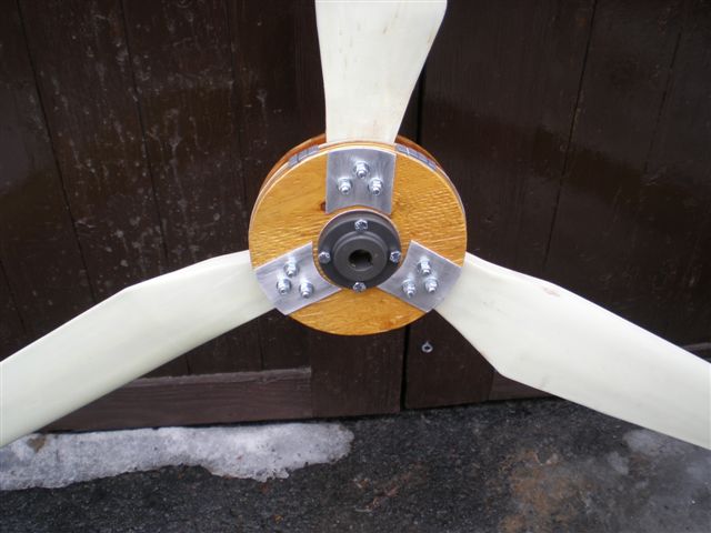
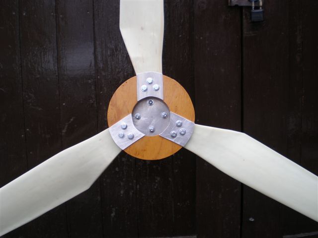
 I carved blades for my Hugh 8 foot wich wor great although only a 6 week run before winter storms. Just for laughs I thought I'd try these chinese fiberglass blades we've all seen on e-bay for this job. This is how I secured them. At 8'8" diameter I'm pretty shure they'll get stalled, but we'll see.

 I'm running a 12v system now but I guess I'll be changing to 48v. Shouldn't be too bad I just need to change my inverter and pour a new 48v stater for the Hugh, please comment.


 What.......Me worry???


 Regards, Jim


i fixed that one photo that did not display properly next time name your photos so they have no spaces in the file names before uploading them.
Kurt
« Last Edit: March 22, 2008, 05:31:38 PM by (unknown) »

Flux

  • Super Hero Member Plus
  • *******
  • Posts: 6275
Re: Motor conversion
« Reply #1 on: March 22, 2008, 11:55:55 AM »
Yes I am sure you are going to stall.


You could do with double the cut in speed for 8ft. Try it anyway but I think you will have to reconnect it to do much good.


Flux

« Last Edit: March 22, 2008, 11:55:55 AM by Flux »

dinges

  • Hero Member
  • *****
  • Posts: 1294
  • Country: nl
Re: Motor conversion
« Reply #2 on: March 22, 2008, 12:02:12 PM »
Jimmy,


I very much enjoyed reading your story.


You have obviously read about other similar projects, studied things, thought things over beforehand (and came up with a few original solutions as well) and paid a lot of attention to detail. Good preparation is a job half finished.


Too bad about the low cut-in RPM but it was to be expected without a rewind. 48V system voltage should improve things quite a bit. Pity the motor was a 600V one to begin with, not a 400V one.


Simply a joy to read about your project.


Peter.

« Last Edit: March 22, 2008, 12:02:12 PM by dinges »
“Research is what I'm doing when I don't know what I'm doing.” (W. von Braun)

coldspot

  • Hero Member
  • *****
  • Posts: 843
  • Country: us
Re: Motor conversion
« Reply #3 on: March 22, 2008, 12:03:00 PM »
 Jim-

Very great looking stuff going on there !!!

 I also have a set of those 102" blades, and two sets of the next size down.

 For the hubs I'm using ones from "NTL". His are a great deal IMHO.

 I have two 2 HP 3 PH conversions done and am still untested on them but getting closer. I hope them are strong enough to stop the blades then shorted out.

 I've been testing my CMI 28lb stepper with ceiling fan blades modded to lifting blades and these at about 4' are just a little to much for this stepper to stop when shorted in 10 mph winds!!!

 makes me think very hard about the furl system !!

 I've got an idea for a "master M J" type pull out of furl, for normal operation, using the pipe over pipe tower top. (I wish I was better on computer skills so I could draw a picture for peoples opinion of it).


 Anyway, our stuff looks great, keep posting about it!


:)

« Last Edit: March 22, 2008, 12:03:00 PM by coldspot »
$0.02

gotwind2

  • Sr. Member
  • ****
  • Posts: 383
  • ben[at]gotwind.org
    • Gotwind - The Renewable Energy Resource
Re: Motor conversion
« Reply #4 on: March 22, 2008, 12:52:32 PM »
I also enjoyed reading your post, clear and informative.

Good images make a world of difference also for me.

I like your attention to detail, including the magnet alignment jig and wooden rotor stand.


I'm sure you will get there in the end.


Ben.

« Last Edit: March 22, 2008, 12:52:32 PM by gotwind2 »

tecker

  • SuperHero Member
  • ******
  • Posts: 2183
Re: Motor conversion
« Reply #5 on: March 22, 2008, 02:04:25 PM »
It's not really hard to cut a center tap into each phase of your stator .  a six point connection will take your cutin up .If it has Y delta connections there's a neutral node to work with .Break out the meter and find 50 %  resistance connection and temp in some connections while on your test jig.
« Last Edit: March 22, 2008, 02:04:25 PM by tecker »

vawtman

  • Hero Member
  • *****
  • Posts: 1425
Re: Motor conversion
« Reply #6 on: March 22, 2008, 03:22:38 PM »
Good job Jimmy,

 I wonder would it help to add 3 more china blades.Just a thought.
« Last Edit: March 22, 2008, 03:22:38 PM by vawtman »

electronbaby

  • Sr. Member
  • ****
  • Posts: 407
  • Country: us
    • Windsine.org
Re: Motor conversion
« Reply #7 on: March 22, 2008, 04:02:36 PM »
yes, very nice job indeed. Im curious to know what make of vinyl ester you used to get a clear casting. Im assuming you did not add filler and therefore it didnt cloud up. If not, the casting could be made stronger with a wrap or two of fiberglass inside your soda bottle. Other than that concern, you did a beautiful job :-)


Cant wait to see how it performs.

« Last Edit: March 22, 2008, 04:02:36 PM by electronbaby »
Have Fun!!!  RoyR KB2UHF

Jimmy D

  • Newbie
  • *
  • Posts: 29
Re: Motor conversion
« Reply #8 on: March 22, 2008, 05:58:47 PM »
 Thanks a lot for the nice comments. Yeah I hooked up a car tail light bulb (12v) across 2 phases and smoked it big time with 2 quick cranks, some times it is just to cool to have made a mistake in this direction.

 All and Flux, this was bench work, from the top of the tower to where the rectifier will be mounted will be 175' of 10/3 AWG would this help a bit extending cutin.

 Thanks Jim      
« Last Edit: March 22, 2008, 05:58:47 PM by Jimmy D »

Flux

  • Super Hero Member Plus
  • *******
  • Posts: 6275
Re: Motor conversion
« Reply #9 on: March 23, 2008, 02:17:40 AM »
In this case line resistance will not help much. It doesn't affect cut in speed.


Where it does help is when the cut in speed is right and the alternator is too powerful above cut in. With the air gap machines the trick is to set the air gap for ideal cut in, then add resistance if you still stall.


In this case if you add enough resistance to do much good in the region above cut in you will not be able to load it in the higher winds. You already have too much resistance but it is within the windings where you can't do much about it.


If you can split the pole groups for each phase and parallel them you can get a better match but breaking into an existing winding can be confusing and difficult.


Flux

« Last Edit: March 23, 2008, 02:17:40 AM by Flux »

tecker

  • SuperHero Member
  • ******
  • Posts: 2183
Re: Motor conversion
« Reply #10 on: March 23, 2008, 09:48:53 AM »
No doubt that small resistance (might be difficult to measure ) on the DC side won't help avoid stall .Also start up at a near 12 volt might be difficult even though the rotor has smooth action the the rollover at 12 as you can see from your tests has some resistance . A  torque wrench is a good tool or a long bar that's the weight of your Blades will give you a good feel for what you need    A different battery configuration will do the trick on your stall. I can understand not wanting to dig into the loom of that stator or even take it apart once you have it finished out .That's a  nice assembly .
« Last Edit: March 23, 2008, 09:48:53 AM by tecker »

Jimmy D

  • Newbie
  • *
  • Posts: 29
Re: Motor conversion
« Reply #11 on: March 23, 2008, 03:22:53 PM »
 Once again thanks, I guess I'll try and fly this thing in the spring. From what I understand it's probably going to spin up, make a few amps, stall, drop out, spin up, drop out etc. Oh well, maybe I'll use it to drag the lake for old outboards :)

 Any ideas appreciated.

Thanks Jim

     
« Last Edit: March 23, 2008, 03:22:53 PM by Jimmy D »

vawtman

  • Hero Member
  • *****
  • Posts: 1425
Re: Motor conversion
« Reply #12 on: March 23, 2008, 03:43:59 PM »
Wish you the best Jim and have fun!
« Last Edit: March 23, 2008, 03:43:59 PM by vawtman »

SparWeb

  • Global Moderator
  • Super Hero Member Plus
  • *****
  • Posts: 5452
  • Country: ca
    • Wind Turbine Project Field Notes
Re: Motor conversion
« Reply #13 on: March 26, 2008, 12:39:41 PM »
Jim,


Your stuff looks fantastic.  I thought I'd chime in because the point about connecting in parallel-delta didn't seem to convince you - but it might help a lot.  Making a "Jerry" connection will also help.


Click on the diagram for full-size.  The parallel-delta is lower right.  This would double the cut-in speed from what you already have.


The way I drew it, only 3 lines are coming out.  You could leave the phases separate, and bring down all 6 ends (that requires a second 10/3 cable, though) and when connected to separate rectifiers (yes, requiring 6 more of those studs) then you could have a Jerry connection, which will give you just a bit more current.


I doubt the Jerry connection would interest you, given the extra cost and time, but if, as you say, you have the star point cut, and there really are parallel windings in your motor (Are there 12 wires hanging out now?) then connecting in parallel delta is worth trying.


I, too, have another motor conversion on the go.  It is also clamped to the bench, with a hand crank on it, just like in your photo!  

« Last Edit: March 26, 2008, 12:39:41 PM by SparWeb »
No one believes the theory except the one who developed it. Everyone believes the experiment except the one who ran it.
System spec: 135w BP multicrystalline panels, Xantrex C40, DIY 10ft (3m) diameter wind turbine, Tri-Star TS60, 800AH x 24V AGM Battery, Xantrex SW4024
www.sparweb.ca