This is a small dual rotor design, that originally was single rotor, poorly designed, and cogged badly !!
Luckly, it was also designed for conversion to dual rotor and dragged out of hiding, to complete that transition!!
The rear rotor, is part of the hub, and the projection you see in the pics, is about 2" in diameter and fine threaded (18 per inch) The front rotor, screws on to the hub, and adjustment is accomplished by turning, in or out -- giving .015" for each 1/4 turn, then two lock screws, drop into the notches you see in the projection, locking the rotor in place.
In my opinion, this was much to complex, for the average builder as it is all machined -- needing both a lathe and milling machine, but has turned out well, for a "one off" machine..
Stator, is 3/8" thick, #20 wire, 75 turns per coil, and 6 coils wired in star 3 phase. (thanks to Flux for tech support)
Rotors are 6-1/8" X 5/16" with groves machined to help hold mags in place, with 8 each --1" X 1-1/4" X 1/4" neos (grade 48) bonded in with Isothalic, resin.
This was so small, it was difficult to turn fast , by hand -- but I estimate an easy +12 volts at about 150rpm and saw 15 volts on faster spins!!
Once I get it up on a tower, I can get more useful info..
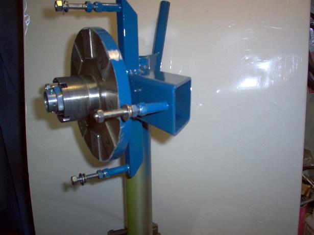
Rear rotor, threaded projection, and bearing adfusting nut..
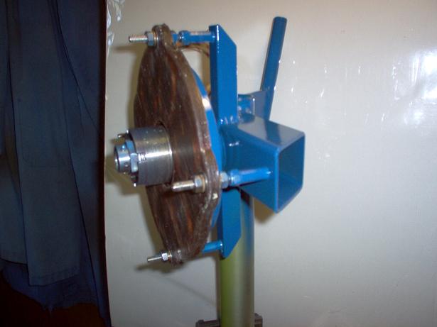
3/8" thick stator plate in place, stainless hardware..
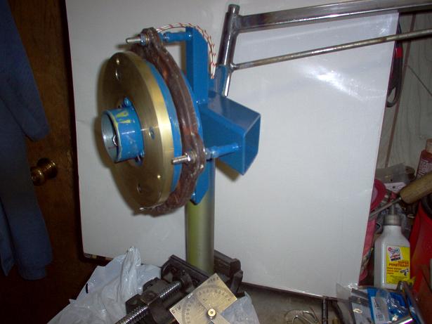
Front rotor in place, with aluminum prop adapter and unfinished, furling tail boom (and scratched up paint)
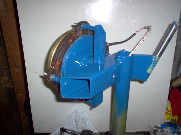
Rear view of assembly -- square tube was used for strength and weight savings--hope you enjoy the pics -- performance specs comeing soon, Bill H....
