Author Topic: My Ahaa! project, auto pitch VAWT  (Read 9494 times)

0 Members and 1 Guest are viewing this topic.

hangar51

  • Newbie
  • *
  • Posts: 6
My Ahaa! project, auto pitch VAWT
« on: July 27, 2006, 02:44:19 AM »
My Ahaa! Project, Auto Pitch VAWM


When I saw a picture of large size VAWT that setting public place like as the Park in some where, I wander why not those Wings have the movable Pitch to up wind, when thinking that, I got suddenly an idea came up my mind, that it!, might be possible pitch control simple devices applied like as "Swash Plate", it was trigger beginning my Ahaa! Project last December, remind that I saw the parts at Home Depot quit a long time before, it's a very large size of flat shape ball bearing made by tin plate, yes remember that time I had a curiosity about who use it? What purpose?


I have not surly plan and nor any reference information, but decided to start build a auto pitch control VAWM project with the condition of: (1).minimize expense as possible I can, (2).look around usable things & available resource. Realize moving object to proof a concept.


If the turbine shaft generates enough Torque, I d rather hooked up water pump but hold any expectation until I get good result on this prototype..


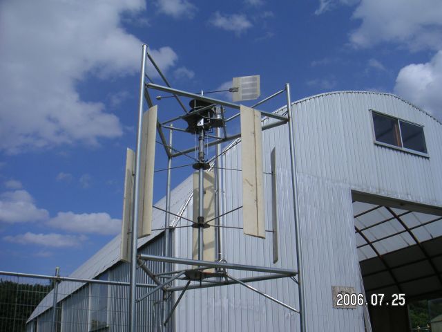
Frame must be rigid and robust for anti-vibration triangle pillar structure by 48mm & 25mm iron pipe.


Wing size: 250mm x 1200mm (Wight 980g) 5 wings supported by upper and lower hub ith spokes lower spoke supports each wing weights and 5 upper spoke have pitch hinge pivot.. avoidance any bent of pipe spoke which may trouble by the friction of inner push-pull rod. So it must be deadly straight without any vertical load. Otherwise change rod to wire.


Possibly "SWASH PLATE" is commercial name??, so I call those units here as "PITCH PLATE" Using two unit of Pitch plate, one is top for whether cook and second fix on gimbals under Frame head. top of free rotating bearing (Pitch plate) is to be fixed have a shallow angle to Rotating axis of weathercock, This plate angle makes displacement by wind direction Changes. From this slant bearing angle (not rotate) draw the information by two thrust rods each other 90 degrees placement. this pitch plate has two vertical rods an, one is connected to out side gimbals frame which set bottom of tower head and the second to inner Gimbals frame keep with 90 degrees position each other.


5 vertical pitch rods connected each bracket on free rotating plate on inner imbals, each rod connected Inner rod in spook through L clank on upper hub, rod end connected each wing hinge, so that wind direction Weathercock pitch plate angle and its element of inclination drive to relatively each wing's pitch angle.


Then when the wing passing rectangular wind direction (against), pitch angle increase To maximum, same time opposite position wing's pitch angle decease, other wing crossing neutral at both of upwind, downwind passing to neutral pitch angle from previous state. Wings angle is not center symmetrical since odd wings count.


About wings trying use the paper honeycomb, but changed taking styrene form core. I did not available to access any NACA Airfoil, so that making template easy way but it is beyond the aerodynamics.


Hand lay-up skin with bidirectional glass mat used with WEST SYSTEM, result of vacuum bagging with handmade perforated vinyl sheet, unfortunately finished many

small dimple both side of wing which caused not apply breather sheet on perforated one, actually I want make smooth wing surface like as Surfing board, however never increase Wight any more, compromised single layer by seems it enough stiffness.


Finally test result is acceptable, several troubles happened and fixed by miner Modification Look like All mechanism has functional as intended, however there seems to be a problem in Durability, tin made ball bearing might be work not so long life, unknown fatigue limit about all pitch control links used ball joint (using Radio Control model parts). Every parts has moving very busy. At now wind was small, scared the frame has happened resonance by vibration when attack the gust or strong wind, So Need more robustness and dynamic balance.


Wind flow was unstable since test place was close the building, I fond that when whether cook stopped some direction, then next wind coming from others, wing tend to rotate backward little bit, But whether cook get turn by threshold, wing turn back leading direction quickly that is almost looks like Jiving.


this time I have no room to use any stainless parts, because almost doable expense.

Unfortunately I have not available web to show other photo, if someone have an interest about all process of my trial and error, I can send those to provided FTP space for photo and video clip.


Now looking for some one have a large lath, I will hand made thrust ball bearing from way-out free Automotive parts. Hopefully next step I will replace 60percent large size (300mm x 1600mm) wing, within 1.5Kg. it is limit of maximum size at same frame, stay rotating Diameter should be 1500mm with some kind of strong spook replaced, now the most question is AIRFOIL, what type is suitable of NACA?


Hangar51.

Latitude:   43.33

Longitude: 144.26


« Last Edit: July 27, 2006, 02:44:19 AM by (unknown) »

willib

  • SuperHero Member
  • ******
  • Posts: 2414
  • Country: us
Re: My Ahaa! project, auto pitch VAWT
« Reply #1 on: July 26, 2006, 09:19:31 PM »
truely amazing hangar51 , i could show you how to make a better airfoil/wing

all you need is a printer to print out the templates for your wing

then cut two cedar shingles the size of the template

attach the cedar airfoils to either end

take a hot wire and remove excess foam .
« Last Edit: July 26, 2006, 09:19:31 PM by willib »
Carpe Ventum (Seize the Wind)

SparWeb

  • Global Moderator
  • Super Hero Member Plus
  • *****
  • Posts: 5452
  • Country: ca
    • Wind Turbine Project Field Notes
Re: My Ahaa! project, auto pitch VAWT
« Reply #2 on: July 26, 2006, 10:36:15 PM »
You have done some intriguing work so far.  When I first set out to build variable pitch VAWT's, I found that I could not avoid a lot of complex moving components.  I eventually abandoned the project when I compared performance of the VAWT to the cost of the components I would have to buy.  But mounting yours in a cage, you have already done better than I did on the safety issue.


If you are looking for data about airfoils, either NACA or more modern, you can find lots of information on the internet at:


UIUC Low-Speed Airfoil Tests


and


NACA Technical Report Server

(Look for NACA TR-824.  If the search engine doesn't have it, I've got it here on my machine, but it's 19Mb.)


The definitive book on all NACA airfoils is Abbott & vonDoenhoff's Theory of Wing Sections, which is still in print.  They are the authors of NACA TR 824, too.


My point of view is that a simple symmetrical airfoil section will work the best.  Test data have been developed for NACA 0012 airfoils by Sandia National Labs that includes when the air flow is reversed over the blade.  These reports are also available on the internet.


I built blades very similar to yours during my original project.  I used a foam core and fiberglass shell.  You vacuum-bagged yours - I'm impressed!  My product was very light, like yours.  This is very appropriate for a VAWT of this size.


Have you fitted the rotor with an alternator?

« Last Edit: July 26, 2006, 10:36:15 PM by SparWeb »
No one believes the theory except the one who developed it. Everyone believes the experiment except the one who ran it.
System spec: 135w BP multicrystalline panels, Xantrex C40, DIY 10ft (3m) diameter wind turbine, Tri-Star TS60, 800AH x 24V AGM Battery, Xantrex SW4024
www.sparweb.ca

veewee77

  • Full Member
  • ***
  • Posts: 244
Re: My Ahaa! project, auto pitch VAWT
« Reply #3 on: July 27, 2006, 08:02:31 AM »
While the whole thing looks great, I have one comment.  Those bearings are for a "lazy susan" which is a shelf in a cabinet that is round and can be rotated for better access.  They are designed to be used on a less than daily access schedule.  In other words, the cabinet may be accessed every other day and then it may only be turned half a turn.  You windmill is constantly in rotation and I am thinking that bearing will not last very long before it is worn out.  Especially if you are in a dusty environment.  Do NOT grease it unless you put it inside of some kind of airtight enclosure.  Dust will collect to the grease and become like grinding compound. Find a better bearing for longevity. . .


Doug

« Last Edit: July 27, 2006, 08:02:31 AM by veewee77 »

electrondady1

  • SuperHero Member
  • ******
  • Posts: 3121
  • Country: ca
Re: My Ahaa! project, auto pitch VAWT
« Reply #4 on: July 27, 2006, 10:28:49 AM »
his is a very nice design, i think you should build it stronger perhaps with the use of automotive  type parts
« Last Edit: July 27, 2006, 10:28:49 AM by electrondady1 »

whatsnext

  • Sr. Member
  • ****
  • Posts: 449
Re: My Ahaa! project, auto pitch VAWT
« Reply #5 on: July 27, 2006, 10:58:05 AM »
'Automotive type' bearing usually have an inordanant amount of preload and would likely prevent his mill from spinning. Some simple, and cheap, conrad types would probably work just fine and be much more durable than the lazy susan bearings he has now while still turning very freely.

John..
« Last Edit: July 27, 2006, 10:58:05 AM by whatsnext »

vawtman

  • Hero Member
  • *****
  • Posts: 1425
Re: My Ahaa! project, auto pitch VAWT
« Reply #6 on: July 27, 2006, 04:05:01 PM »
This proves that vawt builders are artists thats one heck of a sculpture.


 Hope you get the bugs worked out.


 I woulnt think you would need the pitch control if it gives you problems.Maybe just a bigger nose on the foils.

    Carry on Hangar 51

« Last Edit: July 27, 2006, 04:05:01 PM by vawtman »

hangar51

  • Newbie
  • *
  • Posts: 6
Re: My Ahaa! project, auto pitch VAWT
« Reply #7 on: July 28, 2006, 08:03:36 PM »
First, everybody thanks for give me many kind advices and let me know the fact and truth Which I don't know.

Vane chicken (actually used be audio amp cover) with counter weight, and wings are looks like very sensitive, starting by faint breeze and round continues never the less quit amount of inartia (5kg for wings, 20kg for shaft and hubs, spokes).


I like the name of SUSAN!, It my stupid that put on enough grease both of Lazy Susan and Busy Susan, likely much contaminated by particles through Iron works cutting & brushing, must be magnetized balls has lot of iron dust. I am becoming worry about its drive to reduce MTBF half. (now rinsed and cleanup). Disappointed and forget about its reality after the searching alternatives, amazing its very expensive ( @US$700.) at same size ring bearing made by TIMKEN, KAYDON...,  naw awaered that no need such larg inside diameter bearing for wind vane axis, while others indispensable through enough hole for main shaft, some day I will hand made two years life at least substitute BUSY SUSAN. And starting correct the balls (couple of handled) of Automotive Bearing.  


I have never experienced before about any Radio control, so spent almost one month to reach the HROBO & TAMIYA, after look around Junk yard. Concluded no choice other than 6mm diameter ball joint made by HIROBO, anybody know about around 8mm size ball joint industry grade?, it excess size like as gas arm such as car back door for my application, now I aware that never, never grease on ball joint. Even this TOY grade one.


hangar51


« Last Edit: July 28, 2006, 08:03:36 PM by hangar51 »

hangar51

  • Newbie
  • *
  • Posts: 6
Re: My Ahaa! project, auto pitch VAWT
« Reply #8 on: July 31, 2006, 02:48:52 AM »
Hi steven,

Thank you for your advice about airfoil , let me show you space saved photo digest of my building process of wings, first just I want template, it looks like a Fish shape, far from aerodynamics!!, I know definitely you can stop the laughing this evil way, but no choice that time, now I am confused and still can not find best Airfoil for next Wings at low airspeed that assumed 10km/h, stand for the wings rotating 1.5 diameter with 60 rpm. then I have another problem, I have to find out where the best position of fulcram(hinge/pivot) that is fitted on the spar. It may some theoretical point by the formula.

Take a symmetrical airfoil, airspeed should be different each outer surface and inner surface if precisely, does not significant such as small rotation diameter, is this negligible factor such a low airspeed?  How do you think?

Actually form core is not required such spar for structural reinforcement, I have no idea without use the spar to hinge support, so I have to separate the form core for leading section & trailing section at the spar poison that is half inch forward point from checked CG about current wings. Supposed be finished wings became slightly deferent CG poison because 2.5mm thick spar and skin weight added, actually hinge point are half inch from spar surface to trailing edge. So that this point almost near the form core CG. Point is how do you decide a position at your wing before?  Let me know  what number about Your Symmetrical airfoil.   @


« Last Edit: July 31, 2006, 02:48:52 AM by hangar51 »

SparWeb

  • Global Moderator
  • Super Hero Member Plus
  • *****
  • Posts: 5452
  • Country: ca
    • Wind Turbine Project Field Notes
Re: My Ahaa! project, auto pitch VAWT
« Reply #9 on: July 31, 2006, 01:47:01 PM »
Aerodynamic center of wings:


All airfoils have an "aerodynamic center".  That is the point around which all aerodynamic forces act.  Like the center of gravity, around which accelerations can be applied, the lift force and drag forces act around the aerodynamic center.  In most airfoils, the Aerodynamic center is at 25% of the chord.


The center of gravity of an airfoil, on the other hand, is farther aft, say 35-40% chord.  If the spar is near the 30% chord point, you have probably the best trade-off, and it looks that way in your pictures.


Airfoil selection:


Don't worry too much about selecting the airfoil.  The low airspeed prevents any airfoil from matching it's promised values in published tables.  This is a situation where you almost cannot win.  In the slow-start regime, the wind travels backwards over the wing during half of the revolution.  (Note that the aerodynamic center will thus change position to 75% chord, because the wing is travelling backward!)


Drag in reversed airflow is very high and the lift is greatly compromised.  Pitch changes will help by reducing the time in reverse-flow, but not eliminate it.  Pitch changes will improve the angle of attack at any given point of revolution, and that is whay you want to strive for:  optimized Angle of Attack through the entire cycle.


Not easy.  The airflow geometry is constantly changing as the wind changes.


May I also volunteer some terminology to help with the translations (are you using Google's translator?):


SWASHPLATE:  a plate inclined to the axis of rotation to effect a reciprocating motion.


CONRAD BEARING:  a very common type of ball bearing.  Available worldwide.  Cheapest, too.  You just buy complete bearings, not individual balls.  Also available are precision bearings with very small balls that allow very large diameters.  For example, look for NSK 9600 or 9800 series on the internet.


BELLCRANK:   A lever that converts a reciprocating motion in one direction into reciprocating motion in another direction.

« Last Edit: July 31, 2006, 01:47:01 PM by SparWeb »
No one believes the theory except the one who developed it. Everyone believes the experiment except the one who ran it.
System spec: 135w BP multicrystalline panels, Xantrex C40, DIY 10ft (3m) diameter wind turbine, Tri-Star TS60, 800AH x 24V AGM Battery, Xantrex SW4024
www.sparweb.ca

hangar51

  • Newbie
  • *
  • Posts: 6
Re: My Ahaa! project, auto pitch VAWT
« Reply #10 on: August 06, 2006, 09:14:07 AM »
Hi sparweb,

Thank you for your advice, I found nice bearing at NTN dealer, but I am hesitate getting it, and can not make quick decision to buy, because very expensive parts has conflict my first policy, however first model now spinning very well not so remarkable vibration, but sooner later I have to replace befor the bearing wear out.


Finally I had ordered two same size bearing, in this occasion, I will change from fixed angle of pitch to variable pitch angle, for this feature, I have to use large diameter bearing as you can make sense at illustrations. Also things help my decision, neighbors who have large lathe and he let me use short time iron works. I can not make Bearing support parts without large lathe.


Now I have not any measurement tool and how to, so no way to assess the performance, assumed pitch angle is questions, one of method is change the slant NUT which make plate angel to the wind vane axis, Couple of different slant NUT has been changed, now 6.2 degrees used, this result wing Pitch max positive-negative 13.9 degrees, I can not judge its too abundant or just fit.  Another way is change the 5 pivot positions on pitch plate. Seem that pitch should be adjusted when windy.  


Of course now it is a hypothesis, possible it does not work, but concluded that I choose the complexity of links than complexity re-moving the combinations of parts for the variable pitch angle. It may change zero degree to max with steel wire by hand.

.

Now I am thinking about the back lash which occurred at ball joint between bell crank and push rod, when push action, rod axis has turn 1/4 and pull rotate back as same, I have to kill the rod torque that loosing small amount of stroke length.


I have completely no reason make my VAWT with CCW top view; I found peoples wrote papers almost CW top view about VAWT. I am confused that. Should I re-thinking about Hinge structure for next WING?  Is that any connection for alternator?  Nothing the change except pitch hinges structure about me or should I make reversible wings.


http://hangar51@hotmail.co.jp

hangar51

.


« Last Edit: August 06, 2006, 09:14:07 AM by hangar51 »

hangar51

  • Newbie
  • *
  • Posts: 6
Re: My Ahaa! project, auto pitch VAWT
« Reply #11 on: August 06, 2006, 09:41:54 AM »
I have to replace a skematicc, but no way to remove old one. sorry.

hanga51.

http://hangar51@hotmail.co.jp


« Last Edit: August 06, 2006, 09:41:54 AM by hangar51 »

SparWeb

  • Global Moderator
  • Super Hero Member Plus
  • *****
  • Posts: 5452
  • Country: ca
    • Wind Turbine Project Field Notes
Re: My Ahaa! project, auto pitch VAWT
« Reply #12 on: August 14, 2006, 01:02:09 PM »
Hangar51,


Don't worry about the CW/CCW directions.  They make no difference in practice.  They only affect how many negative numbers you have to handle when you do a mathematical analysis or write a computer program.


Now that you have the machine built, do you have plans for an alternator to extract power?  I look forward to hearing about the system's performance.

« Last Edit: August 14, 2006, 01:02:09 PM by SparWeb »
No one believes the theory except the one who developed it. Everyone believes the experiment except the one who ran it.
System spec: 135w BP multicrystalline panels, Xantrex C40, DIY 10ft (3m) diameter wind turbine, Tri-Star TS60, 800AH x 24V AGM Battery, Xantrex SW4024
www.sparweb.ca

hangar51

  • Newbie
  • *
  • Posts: 6
Re: My Ahaa! project, auto pitch VAWT
« Reply #13 on: August 24, 2006, 09:51:49 PM »
SparWeb,

Thank you for you advice, yes I have interest about alternator, before think about this I have to learn much about such as magnet, coil, inverter, and battery for this prototype. Ifm appreciated to great experienced front runners those people has providing me many information, However I guess this VAWT has low RPM for any alternator and too small torque even if drive with reduction pulley but I will try something after the variable pitch control completed.


though the machine had been running very well but happened several trouble by moving parts, aluminum push rod had wear out at both end of steel pipe, caused my basic error that I did not clean up the burr at end face after the metal work, also bell crank was bent by suspected incident wind. I have to replace aluminum push rod to stainless steel shaft. And more stiffens bell crank too.


I have noticed problem on wing that through the motion of it, wing is completely free movement on two pivots if not connected to push rod link to pitch plate, which structure has minimize friction and any resistance of inertia moment. This is guarantee link does follow the pitch plate angle to wing drive. Incidentally, wind has hit the wing with particular angle, then flapping it and one shot make stress to connected link directly.

At now I donft know action method, might be think about put on dumping factor to wing hinge however this increase resistance for push rod movement.. what is my ignorance, so many manufacture for wide range size of grod endh, from 3mm to 15cm. I did not know that and wrong search way by gball jointh. Also aware those are very expensive for armature builder. 8mm rod end should be applicable HAWT pitch arm..  


Ask you patient for my redundant talk by strange English!! About gBicycle pedal effecth which is I will quotation and reference to thesis of IE030801A Appendix D, without authors permission.  I bereave you had read this before.

http://www.integener.com/SABTSKManuscript/AppendixD.htm


long time ago when I visit my friend in Portland Oregon, his favorite things is road race of bicycle, so several racing bicycle stored in his room, that time, I had never been see that kind of gear, I had look first bicycle pedals has strong strap, I understood, it was differ from how of the ordinary bicycle to get on, also when I saw abnormality his developed feet muscle of the thigh.  He explained me that one foot pushing the pedal then other foot pulling up simultaneously so the strap is needed. So that possible to say it is groad race bicycle pedal effectEagainst Auto pitch VAWT. Is there any my fatal misunderstanding?


Now I feel that might be not begin my VAWT construction if I had chance to see and getting information all about wind turbines before start project, though I have not any measurement to correct data for checking performance, so no way compeer to others if its does any small improvement. Then I had becoming believed that simple movable pitch is just small part of dedication for improves to performance. Point is, if I can an extreme expression that pitch control should be self adjustable against both for wind direction and tip speed with some unknown methodology.


hangar51


« Last Edit: August 24, 2006, 09:51:49 PM by hangar51 »