Author Topic: Recumbent Generator - Part #2  (Read 5684 times)

0 Members and 2 Guests are viewing this topic.

FrankG

  • Full Member
  • ***
  • Posts: 121
Recumbent Generator - Part #2
« on: December 26, 2006, 12:16:28 PM »
The Link below is to the second part of the "Recumbent pedal powered generator", that essentialy is a test bed for wind generators...


New Gearing!!!


3-Phase Stator wound & cast in resin!!!


Some basic testing... & even more questions.


http://www.theworkshop.ca/energy/bengen/2/bengen2.htm


FrankG

www.theworkshop.ca

frank@theworkshop.ca

« Last Edit: December 26, 2006, 12:16:28 PM by (unknown) »

Jon Miller

  • Sr. Member
  • ****
  • Posts: 316
  • Country: gb
    • Otherpower UK
Re: Recumbent Generator - Part #2
« Reply #1 on: December 26, 2006, 07:31:53 AM »
Hi Frank,


Good quality work as usual.  I like the idea of using the magnetic sand as a means of pulling in the flux, reminds me of the wood 103 and the use of magnetic sand in that.  Only thing I am thinking, if it's right I can't be sure, but doesn't the magnetic material have to be in a single casting to allow for flux to be continues within the stator.  The set up with the individual castings would course some clogging affects?  Not trying top pick holes just wondering.  Also towards the end of the linked page, you say 32v - 12v = 30v? I make it 20v / 3.2Ohms = 6.25A.  6.25A x 12V = 75Watts. Which when compared to your 50 watt bulb load isn't such an unrealistic loss.  I do like you CAD/CAM machine must have been a lot more work then you can show online.  Whish you luck with future projects.


Regards

« Last Edit: December 26, 2006, 07:31:53 AM by Jon Miller »


stephent

  • Sr. Member
  • ****
  • Posts: 268
Re: Recumbent Generator - Part #2
« Reply #2 on: December 26, 2006, 08:43:30 AM »
Frank, nice looking work first of all.

The math problem cones in where you multiplied the voltage, etc by 1.73---multiply the resistance of each coil set by same amount--1.73 and the result is closer to what you measured. (both sides of the equation have to balance)

Good step by step process on your site, easy to follow.
« Last Edit: December 26, 2006, 08:43:30 AM by stephent »

richhagen

  • Hero Member
  • *****
  • Posts: 1599
  • Country: us
Re: Recumbent Generator - Part #2
« Reply #3 on: December 26, 2006, 06:16:08 PM »
Frank, looking good, by next summer you'll probably be ready for a bike race or two.  I am thinking that as noted above, the flux path would be more efficent if connected between coils, but the iron sand cores should still increase the magnetude of the change in the flux deeper into the coil.  I base this on experiments with one of my first alternators, which used bolts to carry the flux, and had no return path.
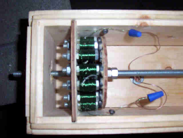


It was not a particularly good design, but it worked for its purpose and shows that even with no return path, the cores effect the flux in the coils.  I think your design will lose some efficiency because of this as well, because you will not see as great of a change in the magnetic field across the coils as you migh have.  That being said, it does work, and appears to work acceptably well at that.  


I have since learned from this site that there are efficiency issues related to the cores as well however.  In the case of bolts eddy currents induced within them contribute to substantial losses, however their are additional losses from the energy lost in the magnetic material due to energy consumed in aligning and realigning the materials magnetic fields, these are called hysterisis losses.  

Of course additionally there are the resistance losses in the copper conductor as well as mechanical friction losses too.  Copper losses and hysterisys losses are to some extent traded against each other in design, and of course we all strive to reduce and eliminate the frictional losses.  


The copper losses can be reduced in design, by using conductors with the least resistance possible.  This means increasing the gauge of the copper, and using as much of the available space as possible.   One way to reduce resistance losses in the wire, is to maximize the change in flux across the conductor, that way fewer turns are required, and larger conductors with less resistance can be used.  I think this is why these axial flux dual rotor air core alternators have become popular for these low power, high efficiency applications.  The magnetic circuit is complete on both sides of the coil, and utilizing powerful neodymium magnets, huge changes in flux can be achieved across the coils with minimal losses due to hysterisis since there is minimal realignment of molecules in the core because the air or plastic is much less effected by the changes in the flux.  


Flux or DanB can probably explain this a little bit better than I , but that is basically how I think of it reigh now.  Rich

« Last Edit: December 26, 2006, 06:16:08 PM by richhagen »
A Joule saved is a Joule made!

FrankG

  • Full Member
  • ***
  • Posts: 121
Re: Recumbent Generator - Part #2
« Reply #4 on: December 26, 2006, 07:42:14 PM »
32-12=20, 32-12=20, 32-12=20, 32-12=20, 32-12=20, 32-12=20, 32-12=20, 32-12=20...


That's that NEW math...


As to the 1.73 X R for Star config, that makes perfect sense... Today & tommorow are are "Shop Cleaning Days" all shelves, benches and cabinets get cleaned out, and any thing that is truly garbage finally will go to the dump. But I hope to try a variety of loads with both Star & Delta configs by weeks end and revist the math.


Rich,


As to Hysteresis (sp?) I can sort of visualize the negative effect of trying to draw the rotating field toward the dense(r) cores... Obviously my intention was to increase the output without a backing plate or second rotor.


So with a either a backing plate or second rotor fixed in rotation with the original the flux lines are static as they cut through the conductors. And the atomic structure is not swivelling within it's domains of alignment trying to seek the cores as they fly past.


There is considerable flux getting through the stator as 5/8" wrench easily sticks to the back of it.


I have cut a second 1/4" rotor disk and will mount it once I have a good base-line of the current set-up.


In a previous post Flux had clearly stated that a second rotor was the way to go and forget about the black sand... I think I'll continue with the coil cores as it makes it relatively easy for assembly (for me at least) but will try plain resin on the next incarnation.


As it stands with the current set-up... I never imagined how much work it is to try and crank-out 50 watts of power for 10 minutes straight. I'm thinking of implementing a 15 minute charging session for anyone that leaves a light on in the house or otherwise is caught grossly wasting energy... (a sure fire way to widen the gap between teenagers and parents) but I'll bet after only a week the point will have been well made.


...fg

« Last Edit: December 26, 2006, 07:42:14 PM by FrankG »

hiker

  • Hero Member
  • *****
  • Posts: 1661
  • BIG DOG
Re: Recumbent Generator - Part #2
« Reply #5 on: December 27, 2006, 03:10:40 AM »
hey frank..


 its all that wire your fighting...

 i built a bike gen a while back--used 53 turns of #14 wire per coil..

 3 phase 8 and 6 combo- dual rotors[12" sawblades] - wired in star..

 used some big block ceramics..

 worked out great--could pedal real easy at 150 watts--like going up a real slight

 grade..things went arye when i hooked up a 400w 38v landing light..was pumping

 like crazy volatage meter was going past 30 volts--BOOM--lost all the mags on one

 rotor--i felt a few fly right past my face!!i forgot to toss the rotor cover on

 in case somthing like that did happen[motorcycle fender]...close call..

 well if you plan on building a new stator use bigger wire and fewer coils

 i built a small dual rotor 7 1/4" sawblade gen also a while back-6and8 combo

 3phase wired in star-#17 wire-think the number of turns was around 100 per coil.

 used ceramics topped off with neoes.. could light up three headlites --but it sure was  

 harder to pedal than the bigger 12" gen.. hope this helps out somewhat...........

« Last Edit: December 27, 2006, 03:10:40 AM by hiker »
WILD in ALASKA

FrankG

  • Full Member
  • ***
  • Posts: 121
Re: Recumbent Generator - Part #2
« Reply #6 on: December 27, 2006, 05:56:57 AM »
Hiker,


AWG#24 - BAD... Boy do I know it...


I really like your idea of a belt-drive off the rim, I would imagine that it would be far quieter then the chains I'm running.


As to 150Watts per your testing, I can't imagine it on my current set-up... I'm hoping that once I get to the point of a second rotor I can start playing with the air gap to adjust the sweet spot for charging relative to the riders cadence or pedalling stride.


Right now it's cutting in at such a low pedal rate, and the progressive resistance to increasing speed feels uncomfortable.


...fg

« Last Edit: December 27, 2006, 05:56:57 AM by FrankG »

The Crazy Noob

  • Jr. Member
  • **
  • Posts: 83
Re: Recumbent Generator - Part #2
« Reply #7 on: December 27, 2006, 06:56:27 AM »
This is a little bit off-topic, but on a recumbent bike, it is better to use a shorter crank size. Something like 140-150mm (kid sized) instead of the more regular 170mm. This allowes for more efficent pedaling and also reduces stress on you knee and hip joints.

I myself am in the process of building a wooden recumbent bike A.T.M. :-).
« Last Edit: December 27, 2006, 06:56:27 AM by The Crazy Noob »

Gary D

  • Sr. Member
  • ****
  • Posts: 442
Re: Recumbent Generator - Part #2
« Reply #8 on: December 27, 2006, 08:22:36 AM »
Frank, you could rectify each phase separately to increase the cut in speed. That would also drop the resistance a bit. Worth a shot, no need for the star connection. Not worth 2 cents, just another option/ test you could perform. Setup looks neat! :-) Gary D.
« Last Edit: December 27, 2006, 08:22:36 AM by Gary D »

hiker

  • Hero Member
  • *****
  • Posts: 1661
  • BIG DOG
Re: Recumbent Generator - Part #2
« Reply #9 on: December 27, 2006, 03:56:45 PM »
frank.


 if it cuts in to early--use a bigger sprocket on the gen..

 it took me awhile to find the right size pully for the 12" gen..

 made a few from plywood--untill i figured out the right size..

 loads of fun...my little 110 gen works great--no need for rects on it

 its wired up with all coils in series--powers my home stereo or small

 13"tv--its a small motor conversion...its only good for about 90 watts

with the coils in series--with each phase rectified it gets close to 280w -then it

can power up a small 110v handdrill or saber saw...heres a shot of the 110v exersise bike--acually it puts out over 300 volts no load--don"t think it would be wise to use outside on a rainy day.......................well good luck on yours...later..


« Last Edit: December 27, 2006, 03:56:45 PM by hiker »
WILD in ALASKA

Bruce S

  • Global Moderator
  • Super Hero Member Plus
  • *****
  • Posts: 5413
  • Country: us
  • USA
Re: Recumbent Generator - Part #2
« Reply #10 on: December 28, 2006, 08:02:54 AM »
The Crazy Noob;

  You'll want to stay with the 170mm size and adjust the seat so that your legs are about 7/8ths fully extended if you want to get the most out of the ride.

Also, if you're building you own, make sure to keep the recumbent angle so that your legs are slightly above the torso , this will make sure you have the correct geometry for longer smoother rides. Mainly it has to do with the blood circulation and all that. The length allows you to keep from getting muscle cramps and all that mess, along with allowing for a smoother ride due to less of a jerky ride.


Also, for less strain, use two shorter chains instead of one long one with a idler in the middle, this will make for a far smoother ride and less chain torque needs on startup.


Hope this helps

Bruce S

« Last Edit: December 28, 2006, 08:02:54 AM by Bruce S »
A kind word often goes unsaid BUT never goes unheard

Seaspray0

  • Newbie
  • *
  • Posts: 37
Re: Recumbent Generator - Part #2
« Reply #11 on: January 02, 2007, 04:38:39 PM »
Nice generator with the bolts.  You'll improve your performance if you magnetically connect the bolts at the back end to complete the magnetic circuit back to the magnets (add a ferous metal strap or something).  You have the gap close on the bolt heads to the magnets, but you've got a considerable air gap at the other end between the bolts.  I like the way you were thinking out of the box to make a generator that wasn't like any of the designs seen here so far.

« Last Edit: January 02, 2007, 04:38:39 PM by Seaspray0 »

richhagen

  • Hero Member
  • *****
  • Posts: 1599
  • Country: us
Re: Recumbent Generator - Part #2
« Reply #12 on: January 09, 2007, 02:14:13 PM »
I actually made that generator a number of years back, before I discovered this site.  I would make quite a few changes if I were to do it over, but you live and learn.  Rich
« Last Edit: January 09, 2007, 02:14:13 PM by richhagen »
A Joule saved is a Joule made!