Over the past week I've been experimenting with various means of getting a cheap, robust and reliable voltmeter for small solar lighting systems. I need it to be cheap, because I'll be building them by the dozen (it's for remote village lighting systems in Fiji, a project which a fellow Otherpower contributor introduced me to).
Anyway, I considered the options available to me:
- Analogue meter - too expensive, subject to corrosion (sea air), you need to be nearby to read it and know what "12.2V" means in terms of battery capacity;
- Digital panel meter - again, too expensive & the number needs interpretation;
- LED meter kit - A bit expensive at $14.92;
- Pre-built LED meter cheaper at $9.97, but I think I can do better. ;-)
- Design and build my own.
Here's the schematic I came up with. The idea was based on my hazy recollection of a circuit from "Dick Smith's Fun Way into Electronics Volume 2", which was being used as a level meter for stereo systems.

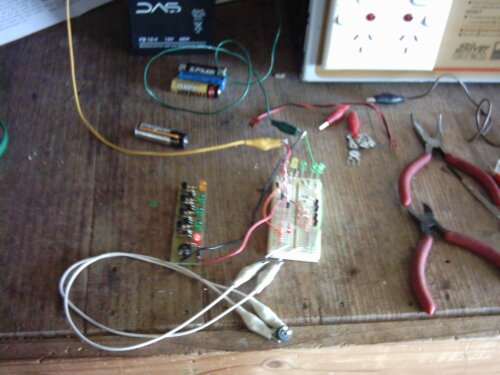
Here's a picture of the finished product, and the prototype on its breadboard:
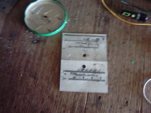
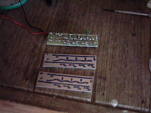
My initial PCB designs, made using a piece of cardboard and a pin:
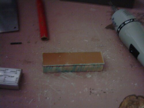
Cutting the blanks out to size - be sure to use a 32tpi blade in your hacksaw!
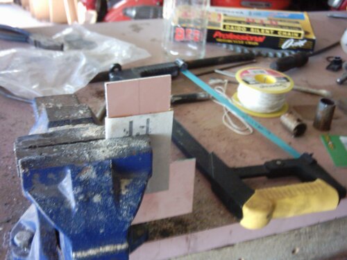
Sicne I'll be making lots of these, I made a drill jig. It's basically a little aluminium box with the pinout holes in the lid, and a block of wood the same size as the blank.
Blank goes on the block:
Jig goes on the blank:
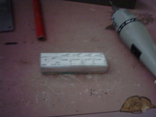
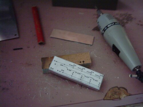
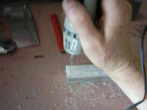
Let's drill some holes!
A finished board on the left, and the drilled blank on the right.
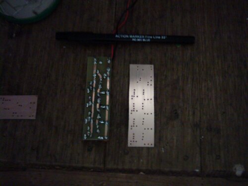
The lands are drawn in place using a special "resist pen" - this is why I decided to go against tradition and drill the blanks first (it makes everything easier to align).
Tie a piece of nylon fishing line through some convenient holes, and dunk the blanks into the warm Ferric Chloride solution for 15 minutes.
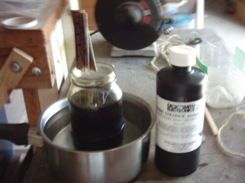
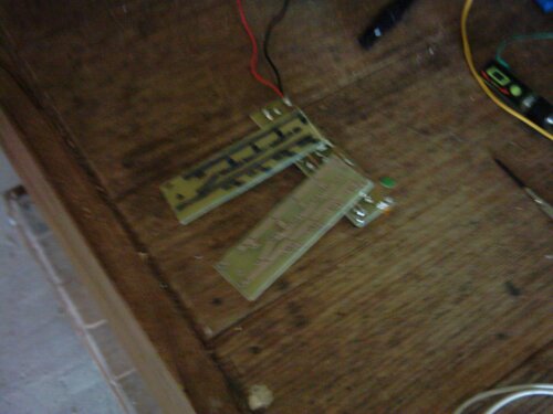
This eats away the copper that wasn't covered with resist ink. I've cleaned up the one on the right with steel wool.
Coming up next, the power box that this was designed for!
BTH
