Author Topic: control schematics  (Read 1713 times)

0 Members and 1 Guest are viewing this topic.

newguy

  • Newbie
  • *
  • Posts: 41
control schematics
« on: February 16, 2005, 04:50:49 AM »
i found this dc current regulator i was wondering if it would work well for a windmill application


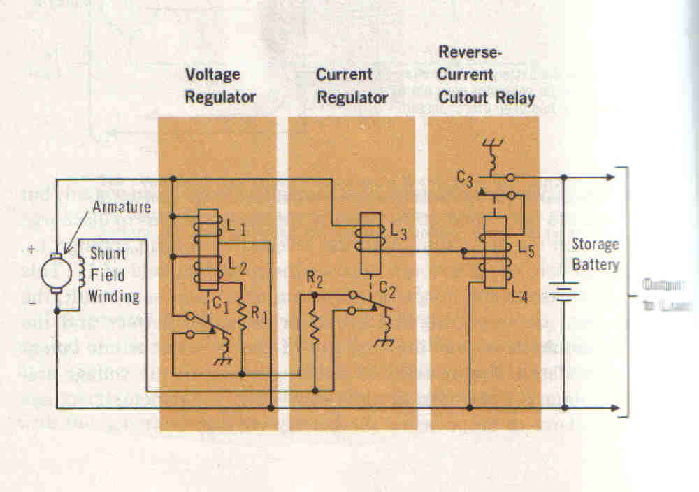
Electricity 1-7 by Harry Mileaf


I built my machine according to hugh's plans but here is the break down

  the coils have 300 turns of #20 wire 9 coils

when the generator is spun at 60rpm one coil is about 5.2 acv

  it only has one rotor with magnets on it but there is another steel disc on the othere side of the stator i used the 1.5x2x.5 inch neo's

  there are five brige rectifiers that are 35 amp 600 volts

the rectifiers are connected in parralel  

it is a two blade machine

the blades are 8 foot dia carved to hughs plans  

the wire coming down the pole is #12

i have a 60 amp ammeter


What i want to know is what size type of components will i need to get so everything works out. my windmill is a 48v machine but i want it to charge at 12 volts will that schematic do this

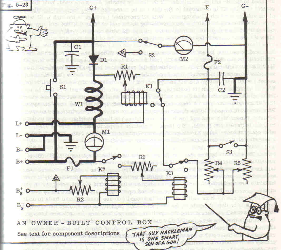
i found another schematic by michael hackleman for a windgenerator controll box man that guy is a genius


any coments will be helpfull

also thanks to admin for the FAQ which i just viewed it is very helpfull

« Last Edit: February 16, 2005, 04:50:49 AM by (unknown) »

domwild

  • Sr. Member
  • ****
  • Posts: 357
Re: control schematics
« Reply #1 on: February 15, 2005, 11:12:02 PM »
Hi,

Not having a black belt in electrickery I can see it contains a lot of relays and lots of Amps meaning lots of sparking and arcing. Switching gets done these days with semiconductors but if this setup works, then it is OK.
« Last Edit: February 15, 2005, 11:12:02 PM by (unknown) »

Epower

  • Newbie
  • *
  • Posts: 16
    • Match-ett Science 4 All
Re: control schematics
« Reply #2 on: February 16, 2005, 01:05:41 AM »
I believe this is a voltage regulator control system which was used on all GM cars during the 60`s and below.  Why I know, is because my 1967 camaro had this relay type regulator and it worked fine. It lasted for years without any problems. The alternator in those days were in the range of 35 amps or so. I am sure the regulator is still around. Maybe at an auto junk yard nearby. The size of the regulator in my car was approx. 3.5" L x 2.75 W x 1.75"deep. Just a little info, hope this helps you out....Epower
« Last Edit: February 16, 2005, 01:05:41 AM by (unknown) »

drdongle

  • Hero Member
  • *****
  • Posts: 552
Re: control schematics
« Reply #3 on: February 16, 2005, 04:29:33 AM »
Well if you want to reduce the out put to 12V from 48V neither of the schematics above will do the job, they will provide a measure of regulation for the generator for which they are designed but not voltage reduction/ conversion. What you need it a DC to DC converter.

May I make a recommendation... please read the archive of articles here at fieldlines, many of your questions will be answered in those articles, yes it will take some time to go through them but it will be time well spent, you will learn A LOT!!
« Last Edit: February 16, 2005, 04:29:33 AM by (unknown) »

Flux

  • Super Hero Member Plus
  • *******
  • Posts: 6275
Re: control schematics
« Reply #4 on: February 16, 2005, 04:37:47 AM »
These car regulators work by changing the field current. With permanent magnets there is no way you can use them.


To charge 12v batteries properly you need a winding that is matched to 12v.


You say that you followed Hugh's plans, but you seem to have changed everything.

You may be able to reconnect it for 12v but your description is too vague to be able to tell. Hugh's design uses 10 coils, if you have used 9 how have you connected it?


If you have connected it 3 phase you may be able to connect in delta but why 5 rectifiers for 3 phase.


Flux


« Last Edit: February 16, 2005, 04:37:47 AM by (unknown) »

jimjjnn

  • Hero Member
  • *****
  • Posts: 511
Re: control schematics
« Reply #5 on: February 16, 2005, 05:34:31 AM »
Been lots of years since I last saw and old DC generator regulator from the 60's. My Corvair had one similar except for the adjustments. Hated the damn thing. Radio always had static. Had to change the capacitor on the L terminal a lot.
« Last Edit: February 16, 2005, 05:34:31 AM by (unknown) »

newguy

  • Newbie
  • *
  • Posts: 41
Re: control schematics
« Reply #6 on: February 16, 2005, 06:38:15 PM »
sorry i meant ten coils but thanks anyways i guess
« Last Edit: February 16, 2005, 06:38:15 PM by (unknown) »

Flux

  • Super Hero Member Plus
  • *******
  • Posts: 6275
Re: control schematics
« Reply #7 on: February 17, 2005, 12:52:15 AM »
Sorry, if you have 10 coils it is already fully in parallel and you can't reconnect it.


If the need for 12v is temporary and you intend to change to 48v you may be able to get some sort of performance with a few ohms in the line to raise the speed. If you can use the heat all the better.


The only long term solution is to make a new stator with the right number of turns for 12v.

« Last Edit: February 17, 2005, 12:52:15 AM by (unknown) »

newguy

  • Newbie
  • *
  • Posts: 41
Re: control schematics
« Reply #8 on: February 17, 2005, 05:28:10 PM »
hey thanks a lot i played around with

the air gap between the stator and the magnet plate last night

it was an 1/8 of an inch i increased the gap an 1/8 every time

and tested the ouput dc of the machine at 60rpm i found that

if i open the gap to 1/2 it significantly reduces the voltage i

guess because of less flux right but according to how i was thinking

with an 1/8 air gap it takes 90rpm to get around 50vdc so with the 1/2

air gap it would take around 300 rpm to get 14vdc could this work i mean

is it safe reliable temporary what do you think

thanks
« Last Edit: February 17, 2005, 05:28:10 PM by (unknown) »

Flux

  • Super Hero Member Plus
  • *******
  • Posts: 6275
Re: control schematics
« Reply #9 on: February 18, 2005, 01:29:44 AM »
yes that is a perfectly satisfactory way to do a temporary fix but there are a few snags and things to watch.


Set the air gap to give you a suitable speed to match your blades for the cut in speed you want ( say 7 mph in a low wind area or 10 in a good area) . Your output will have to be limited to the safe working current for the wire of your 48v stator so you must be prepared to accept only about 1/4 of the power that you could get at 48v. This may present a problem as your tail weight may be too great.


If you find that you can't keep the output down to a safe level, try closing the air gap a bit and with a bit of luck you will be able to control it with a combination of furling and blade stall.


If you play around you should get good results in very light winds and still keep it safe at the high end but with poor top end power.


good luck


Flux

« Last Edit: February 18, 2005, 01:29:44 AM by (unknown) »