Author Topic: A fun project  (Read 1436 times)

0 Members and 1 Guest are viewing this topic.

RobD

  • Full Member
  • ***
  • Posts: 116
A fun project
« on: June 19, 2005, 09:03:06 PM »
I'm designing an inexpensive gauss meter kit (should be out later this year) and here's a part of the circuit that lets you see what the pole of a magnet is (north or south) by lighting two different color LEDs.


Here's the circuit, I'll be posting it on my site with details for those of you who want to build it. (Please no commercial selling,thanks)

RobD

« Last Edit: June 19, 2005, 09:03:06 PM by (unknown) »

RobD

  • Full Member
  • ***
  • Posts: 116
Re: A fun project
« Reply #1 on: June 19, 2005, 03:11:04 PM »
Here's a better schematic:


« Last Edit: June 19, 2005, 03:11:04 PM by (unknown) »

laskey

  • Jr. Member
  • **
  • Posts: 55
Re: A fun project
« Reply #2 on: June 19, 2005, 05:24:00 PM »
I'd only make a few changes.  First, the Hall effect device you are using is BiCMOS (if I read it correctly) and will operate at 8 volts, and so will your voltage comparators (up to 16V)... So instead of turning 4 volts into heat with the 7805, I'd use a 7808, amd only turn 1 volt into heat.  


Then I'm pretty sure you can rig that comparator to swing positive and negative, then you'd only use one, and you can install one of the resistor-LED legs parallel to the other set and backwards.  So when the comparator goes positive one led lights, and when it goes negative the other lights.


That's my two cents,

Cya,

Chris

« Last Edit: June 19, 2005, 05:24:00 PM by (unknown) »

RobD

  • Full Member
  • ***
  • Posts: 116
Re: A fun project
« Reply #3 on: June 19, 2005, 08:34:47 PM »
Chris,

Thanks for your input.

First the max B+ of the Hall is 8 volts but I never run a chip at it's absolute ratings.

Secondly, the 3702 is a dual chip so it has two comparators. I try to use all the inputs to keep the noise to the chip down as much as possible.

Using 8 volts also means that the insertion loss of the 78L08 which is about 1.2 volts would mean the regulation would drop out as the 9 volt batteries voltage fell (long before its useful life was over). With a 5 volt regulator their is much more 'headroom' and the battery actually lasts longer because it can run the circuit down to about a 6.0 volt battery level before it starts to fail.

Also the circuit only uses about 4ma. with power on and no magnets in the path and about 12 ma. with an LED on. It should last quite awhile.

RobD
« Last Edit: June 19, 2005, 08:34:47 PM by (unknown) »

commanda

  • Hero Member
  • *****
  • Posts: 731
Re: A fun project
« Reply #4 on: June 20, 2005, 12:07:15 AM »
I think the point of 2 comparators is so that both leds are off when not in the presence of a magnetic field.


Amanda

« Last Edit: June 20, 2005, 12:07:15 AM by (unknown) »

drdongle

  • Hero Member
  • *****
  • Posts: 552
Re: A fun project
« Reply #5 on: June 20, 2005, 04:50:05 AM »
As to eliminate the regulator simply feed 9 volts directly to the opamps and then feed it through 2 or 3 1N4001 rectifiers to drop the voltage to 7.8 or 7.2 for the hall device. It would also seem to me that it would work with 1458's as well, an IC I have bunch of and which is cheep and very available. You could also use a dual color LED to make it look slick. AC fields would make it light yellow.

« Last Edit: June 20, 2005, 04:50:05 AM by (unknown) »

RobD

  • Full Member
  • ***
  • Posts: 116
Re: A fun project
« Reply #6 on: June 20, 2005, 07:15:52 AM »
Doc,

The regulator gives a good base for the comparator and reference voltages which diodes wouldn't do. (As battery voltage changed so would the reference.) Also the reg. cost about 24 cents and I buy diodes in the hundred for about 8 cents each now so three would cost about the same as the reg.

I like the comparator over the 458 series op amp but sure use what's in you parts bin. That's how this got built!

I like the dual colored LED, never thought of that.


Amanda, yes you're right.


Also the on/off switch is push button so I imagine the battery will last for years!


It really works neat and I'm walking around here checking every magnet I can find! And that's a lot of magnets!!


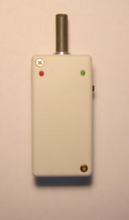
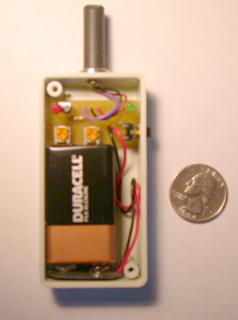
Here are a couple of photos. (The 3702 is SMT and under the board)

The 'nose' was machined from aluminum and heat tubing was placed over it after the wires were run. The whole project took about 2 to 3 hours.


« Last Edit: June 20, 2005, 07:15:52 AM by (unknown) »

laskey

  • Jr. Member
  • **
  • Posts: 55
Re: A fun project
« Reply #7 on: June 22, 2005, 11:22:14 PM »
Ah, but of course you're right.  It makes sense to me now that you explain your reasoning.


Very nice, I'd like to build one myself.


Cya,

Chris

« Last Edit: June 22, 2005, 11:22:14 PM by (unknown) »