Author Topic: Small scale solar MPPT wins 21%  (Read 14426 times)

0 Members and 1 Guest are viewing this topic.

elt

  • Sr. Member
  • ****
  • Posts: 328
Re: Small scale solar MPPT wins 21%
« Reply #33 on: September 17, 2008, 08:34:49 PM »
Hi Scott,


Let me test my understanding...


C = 5 amps * .000008 seconds / .030 volts

C = 1,333 uF


Since caps loose their uf over time, probably want larger value?


> Current monitoring - Analog switch to capture peak current in FET.


I'm not sure how an analog switch would do that but since R (isn't "R" = Rdson?) is fixed, isn't peak current at the same time as peak voltage... which would be just as the inductor is turned on? Then why not sample that with the micro's ADC?


> ADC must sample at the LC time constant or slower. Input Cap.


I google nil on LC time constant. Is that perhaps RC with R being the R of the coil or maybe LR with R being the R of the FET or do I need to keep looking for "LC"?


I'm guessing RC ... I'm using a JW Miller 2312-V-RC with a DCR of .037 ohms times .001333 farad = 49 uS. That's 20KHz or slower so that's okay.


Okay. I still think that peak current(FET voltage) will vary strictly with duty cycle but, if I understand, cap voltage will drop as the panel is loaded so cap volts times FET volts will vary as the power does and I can use that to direct towards MPP.


Well, I did go off track?


BTW, the reason that I keep hanging on to using the micro's ADC on the FET is that the timing of the sample and hold is very well defined and even though it has to be started before the PWM pulse, it can be scheduled to an accuracy of a single clock cycle. Also, while the aperture on the sample and hold is many clock cycles, the cap itself is only 14 pf (if I read the data sheet correctly) and I think (read "guess") that that will respond in sub-microsecond timing.


What do you think?


Thanks again!

- Ed.

« Last Edit: September 17, 2008, 08:34:49 PM by (unknown) »

scottsAI

  • Hero Member
  • *****
  • Posts: 884
Re: Small scale solar MPPT wins 21%
« Reply #34 on: September 18, 2008, 12:57:13 AM »
Hi elt,


I had made an error in my cap size, so suggested 0.03v thinking it would only be 10uf.


The current should be the panels current.

Your test example above is few watts?

Was the 5 amps the peak inductor current? Or do you have 85w panel just waiting to be used?


I would not use a cap that big.

The voltage change can be larger than 0.03v, lets try it again with 0.1v to get a more reasonably sized cap. Like 400uf, much better. For over temp and life 470uf works. Assuming 5a and 8us.

The cap only needs to supply the current when it exceeds the panels capability, which it must so the average current in the inductor is equal to the panels peak power point current:-)

Realized inductors current is above the panels for less than half the time, the cap can be sized to half the above calculated. 250uf.


The ADC must be protected from the Battery voltage across the FET after it turns OFF.

The FET's voltage should be captured just BEFORE it turns OFF. When Inductors current will be at its peak. If you can protect the ADC input and measure it at the right time then great! Do what ever works. Input voltage to ADC must NOT exceed its supply voltage.


LC time constant = square root (LC)

After making a change to the on time (Ton) wait LC time constant before making a decision.

The capacitor will supply extra current for a few cycles before the system stabilizes to the new condition. Looking too soon can miss lead you into thinking you can transfer more power than is available. Nothing wrong with waiting even longer, just don't want seconds to go by.


"Okay. I still think that peak current(FET voltage) will vary strictly with duty cycle"

Go back and look at the panels output voltage vs current.

Starting out the panels output is limited by the output voltage.

As the load current increases the output voltage droops a little but is more or less constant.

As the load exceeds the POWER capacity of the panel, the voltage crashes as the current is increased to the shorted condition. Without a cap before the inductor, when the inductor's current exceeds the panels current limit, the voltage will drop preventing the inductor's current from increasing, the inductor may give back...


The driving force for an inductor is Voltage.

Using your inductor as an example, with 20v across it what will the current be in 8us? Then try that with 10v? Current will be half at the end of the same 8us.


Have fun,

Scott.

« Last Edit: September 18, 2008, 12:57:13 AM by (unknown) »

elt

  • Sr. Member
  • ****
  • Posts: 328
Re: Small scale solar MPPT wins 21%
« Reply #35 on: September 19, 2008, 07:31:15 PM »
Hi Scott,


Okay, I've been looking at the other part of the curve...


Here's an example of an inductor voltage(yellow) vs FET off time(purple) plot that my simple simulator shows:


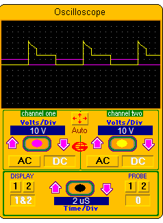
This is 17 volts in at 1 amp, 29 volts out, period = 20uS and duty cycle 50%


I think that the integration of the first part of the waveform is directly related to input power, if that can be done then no other sensors are needed for MPPT.


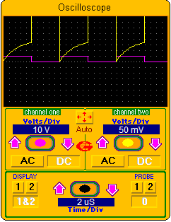
Also, no calculation would been needed for the off-time as the FET voltage drops to the input voltage as soon as it droops below the output voltage. (In this simulation, the FET is off for about three times longer than it should be.)


> The FET's voltage should be captured just BEFORE it turns OFF. When Inductors current will be at its peak.


Okay, I have to turn up the gain on my pretend o-scope to see the FET on-time...


... I think that you are saying that, with the proper sized cap, that I can use the current calculated from end of that curve times the voltage across the cap as the power calculation?


> If you can protect the ADC input and measure it at the right time then great! Do what ever works. Input voltage to ADC must NOT exceed its supply voltage.


Okay, what I was thinking of was putting a voltage divider in there to get the peak voltage below Vcc but then running it into the 20x gain stage. Not sure yet but am thinking that Vcc or less presented to gain stage might saturate the ADC at higher volts (but not blow anything) yet still amplify the lower voltages to get more accurate readings there.


I can schedule the sample and hold aperture on the ADC to the clock cycle and guess that with its 16pF capacitor that the value held will be the voltage very close to the end-time of the window. I haven't done the programing yet but think that by sliding the aperture across a few PWM cycles that I can super sample the discharge curve and get a fair digitization of it... just theory at this point.


> Was the 5 amps the peak inductor current? Or do you have 85w panel just waiting to be used?


I wish! In a nutshell, I hope to get a Harbor Freight panel set and test the three panels both in parallel and in series. I'm guessing that bucking will be better than boosting but would like both circuits to handle two or perhaps three sets of panels. I can't invest much in solar right now but think that 5 amps could conceivably be a lot of watts in the buck version ...


How does that sound?


- Ed.

« Last Edit: September 19, 2008, 07:31:15 PM by (unknown) »

scottsAI

  • Hero Member
  • *****
  • Posts: 884
Re: Small scale solar MPPT wins 21%
« Reply #36 on: September 19, 2008, 10:13:52 PM »
Elt,


I do not understand your plots. Need plots like:

http://en.wikipedia.org/wiki/Boost_converter

Please use this for a discussion:-)

Fig 3 shows inductor current, input and output voltage, on / off time.


Inductor current should be ramping up with FET on.

Output voltage boosted while FET is off, inductors current decreasing.


Output power = IV, with a fixed output voltage, by maxing current we max power.

The inductor currents wave form is the same each time just maybe higher / lower.

Therefore by maxing the peak = max power, only one sample is required.

Exactness is not required, if all samples are acquired the same way, method needs to show relative size. If bigger shows up as bigger and vice versa, should be good enough.


Boosting maybe better. If series connected panels are exactly the same then same.

My panels are not the same, expecting 15% more power by boosting each separately.


Bucking can be better if the voltage is high, thinner wire back to battery where its bucked down...

Many ways to look at this!


What simulator are you using, do not recognize pictures.


Have fun,

Scott.

« Last Edit: September 19, 2008, 10:13:52 PM by (unknown) »

elt

  • Sr. Member
  • ****
  • Posts: 328
Re: Small scale solar MPPT wins 21%
« Reply #37 on: September 20, 2008, 09:09:42 AM »
Hi Scott,


I think we're looking at apples and oranges... er, coils vs. FETs. My toy-ish simulator only gives me a virtual DVM and virtual oscilloscope for analysis. Yes, if I put the leads across the coil, then I get results similar to fig.3.


I thought that we were going to measure the voltage across the FET? As I understand fig.3, the FET voltage isn't shown.... The plots I posted simulate the standard boost circuit with the o-scope ground on ground, channel one on gate and channel two on drain.


The duty cycle in this sim was 50% and is seen by the square waveform in red. The voltage on the drain-source channel (yellow) is at 10v/div when the FET is turned off and shows a quick voltage spike to 50 volts or more that trails off until the voltage drops below battery volts (about 30v), then it slams down to input volts (about 17 volts).


The second image shows the voltage across the FET when it is turned on. Channel two is set to 50mv/div to show the detail during this phase. ( The voltage looks flat in the first image but it's not, it's just lost in the larger voltage scale.)


If I understood your instructions, I am to measure the FET voltage just before the FET is turned off, that would represent the approx 150mV shown on channel two in the second image.


If I understood your instructions, the volts measured just before the FET is turned off would be multiplied by the voltage across the cap. Power = Vcap * Vfet/Rdson but R is constant for purposes of relative comparison so forget about it. Is that right?


That seems to represent maximizing power in from the solar panel. When you first wrote of measuring current by using Rdson as "the shunt", I assumed you meant on the output (battery) side. Based on that, I was suggesting that the "tall area" in the left hand part of the yellow waveform in the first image, starting just after when the FET gate is turned off until the voltage drops below battery volts represents the power that is transferred to battery. Now we're considering (Vds x Rdson) x Vbatt. Similar to the previous case, Rdson is fixed and can be dropped from the calculation but now Vbattery is constant for purposes of relative comparison so we can forget about it as well. All that leaves to consider is volts across the FET for as long as the diode is conducting. From what I've seen from a few different input-power setups, I'm suspecting the using the diode conduction time alone might be adequate to track the MPP... hm, "maximizing conduction time of diode with a pwm output" sounds like a good description for MPPT on a chip.


Do you have an analog solution? I know that many folk would prefer an analog solution but it seems hard for me to beat the functionality of a two dollar microprocessor chip.


Is this making any sense?


 - Ed.

« Last Edit: September 20, 2008, 09:09:42 AM by (unknown) »

scottsAI

  • Hero Member
  • *****
  • Posts: 884
Re: Small scale solar MPPT wins 21%
« Reply #38 on: September 20, 2008, 09:04:18 PM »
Hi Elt,


We are on the same page! Some clarifications:

I assume Vcap is the capacitor on the Solar Panels side?

Power = Vcap * (Vfet/Rdson) / 2, correct for the panel side.

Inductor Current is a ramp must Divide by 2 for the average current:-)

As the panel is loaded Vcap will change (a lot), therefore power is dependent on it.

As you state Rdson cycle by cycle is the same (dependent on temperature)


The energy in the inductor is the same for the charging and discharging equations:

Power = Vbat * (Vfet/Rdson) / 2 (if discharging current is a ramp)

Since Vbat is constant only need to max Vfet to Max power!

If discharging is not ramp not sure if valid comparison? Need to think about this.

Time PWM cycle to keep some current in the inductor at the end of the cycle to get ramp.

(As long as the load side conditions remain the same, expect OK to let current go to zero.)

Then comparisons of peak currents are representative of more energy = more power.

Power transfer with inductor current going to zero requires larger Peaks currents to get the same average. 4 = 8/2, if current goes from 2 to 6 = 4 same average current.

Peak currents are the root of most problems in a switcher.


Timing the length of inductor output is more difficult than measuring Vfet once.


Do you have an analog solution?

No, I could...

Couple years ago saw a very complex circuit doing MPPT. Much more Costly.

May have been in a patent. (where I go to learn how things work:-)


Have fun,

Scott.

« Last Edit: September 20, 2008, 09:04:18 PM by (unknown) »

elt

  • Sr. Member
  • ****
  • Posts: 328
Re: Small scale solar MPPT wins 21%
« Reply #39 on: September 21, 2008, 01:56:33 PM »
Scott wrote:


> Timing the length of inductor output is more difficult than measuring Vfet once.


!!!


Can it be that simple? Timing the inductor output is free when using a 16 bit timer for PWM on the AVR micros. Simply set up the input capture unit to trigger on the analog comparator...


I'm going to restart this reply down at the bottom of the page; in thread-view mode we are so far to the right of the page that only little words will fit on the screen...

« Last Edit: September 21, 2008, 01:56:33 PM by (unknown) »

elt

  • Sr. Member
  • ****
  • Posts: 328
Re: Small scale solar MPPT wins 21%
« Reply #40 on: September 21, 2008, 02:25:29 PM »
This continues as a reply to scottsai that way off to the right of the page...


Scott wrote (way back here):


> Timing the length of inductor output is more difficult than measuring Vfet once.


Can it be that simple?


Timing the inductor output is free when using a 16 bit timer for PWM (on the AVR micros.) Simply set up the input capture unit to trigger on the analog comparator. Compare the voltage on the FET side of the diode to the battery voltage and use the value recorded as the PWM on-time. If the capture value is equal to or greater than the on-time, increase the on-time until you see the inductor time lag. The built-in noise canceler adds four clock cycle to the compare timer so that can be taken into account when setting the duty cycle. I've got the input capture pins available on the test rig (pictured above) so I ought to be able to wire that up for testing...


> Couple years ago saw a very complex [analog] circuit doing MPPT.


... am still thinking that MPP tracking based on targeting 70 or 80 percent of the panel's open circuit voltage might enable a simple analog solution but I haven't found a fast and cheap sample and hold chip; for me, the $2 micro is hard to beat.


- Ed.

« Last Edit: September 21, 2008, 02:25:29 PM by (unknown) »

scottsAI

  • Hero Member
  • *****
  • Posts: 884
Re: Small scale solar MPPT wins 21%
« Reply #41 on: September 22, 2008, 02:21:56 PM »
elt,


> Timing the length of inductor output.

Timing the inductor output is free...


Please show me this Free measurement?


Can sample and hold the FETs voltage for 18 cents in parts from DigiKey. Unit One.

Using 10 Bit ADC, can skip amplifier. May need to average several samples... not a problem.


>thinking that MPP tracking based on targeting 70 or 80 percent

You could be right. Question most panes OCV is like 20v, loaded is 17v or 85%??

In your first post using about 10 watt solar panel with 44uf.

Less than 1ms needed to get OCV.


Have fun,

Scott.

« Last Edit: September 22, 2008, 02:21:56 PM by (unknown) »

elt

  • Sr. Member
  • ****
  • Posts: 328
Re: Small scale solar MPPT wins 21%
« Reply #42 on: September 22, 2008, 04:29:16 PM »
Hi Scott,


>Free measurement?


You got to remember that "free" to a software guy means no (or little) code...


The input capture unit (included on most 16 timers in AVRs) can time stamp the analog comparator. Use the same timer for PWM and capture and then you get the pulse end time in the input capture register. The pulse with will be contents of the capture register - PWM match register.


Unfortunately, my favorite TINY85 doesn't have a 16 bit register but an ap note shows how to time the analog comparator with just a few cycles of latency. (The less expensive TINY2313 and the larger footprint TINY84 both have 16 bit resisters and can do the timing without polling the comparator bit.)


> Can sample and hold the FETs voltage for 18 cents in parts from DigiKey.


Please, how? Darned if I could find anything fast enough for less than $12 USD (but all I know to search for is "sample and hold")


I didn't think an ADC would be needed. I was thinking something like a JK flipflop, two comparators and a sample and hold.


Drain voltage dropping below battery volts would turn on FET, the panel voltage dropping below x% of the panel's OC voltage would turn off the FET. The only trick is a little delay is needed after the drain voltage drops to the OC panel voltage do the sample and hold before the FET can be turned back on... I think that works in theory but not sure if it's doable.


Does that make any sense?


 - Ed.

« Last Edit: September 22, 2008, 04:29:16 PM by (unknown) »

scottsAI

  • Hero Member
  • *****
  • Posts: 884
Re: Small scale solar MPPT wins 21%
« Reply #43 on: September 22, 2008, 06:08:26 PM »
Ed,


Sample and hold:

I will give you a hint, let you discover it, if cant then I will tell you?

Parts are 2N7002 and 30nf cap.


Free measurement: Not so free:-)

Circuitry is required to detect the voltage above panel. What is this in parts? What does it cost?


Yes I understand about the software, input capture etc.

I have spent as many years programming micros as Hardware design.

The Freescale RS08 has 16 bit reg for capture 20 pins. 99 cent in 25 quantity!


Have fun,

Scott.

« Last Edit: September 22, 2008, 06:08:26 PM by (unknown) »

elt

  • Sr. Member
  • ****
  • Posts: 328
Re: Small scale solar MPPT wins 21%
« Reply #44 on: September 22, 2008, 07:43:53 PM »
> Sample and hold:


Okay, I think I'm close; I could see a p-fet charging the cap and then turning off to hold; do I need one of them high side drivers to use the same with am n-fet? I'll throw this in the simulator and see what happens...


> Not so free:-) Circuitry is required to detect the voltage above panel. What is this in parts? What does it cost?


Okay, no incremental cost because I want to make a charge controller as well. But for MPPT only, that'd be a buck for the micro plus 4 resistors to make the two voltage dividers. Add twenty-five cents more to move up to a temperature compensated charge controller.


RS08!? No.No.No.No. I went to Freescale on two designs because they cost less; used the RS's big brothers: a QT60 in a Zigbee radio and a GB80 on a remote sensor board. I probably popped 40% of the chips just programming them and half of what remained in use in the field. I usually got pins shorting to high current; not just on the I'm-not-an-EE boards that I designed myself but the OEM Zigbee radios boards I bought as well. Now I have to stock chips for repair. Makes me very skittish every time I put a BDM cable on one. They seem fragile to me (though I really do like CodeWarrior for development.)


Perhaps I don't have an ESD Best Practices procedure in place here but on the other hand, I've never burned an ATMEL chip unless it really, really deserved it and certainly never just by handling it or a board it was in.


> >thinking that MPP tracking based on targeting 70 or 80 percent

> You could be right. Question most panes OCV is like 20v, loaded is 17v or 85%??


I think that a fix boost calculated to do 17v to 29v would work fine for good panels in full sun. I know there's some power in party-cloudy but I honestly don't know whether it's worth the extra dollar to get MPPT or not. One big advantage of spending a dollar for the micro, though, is that it can automatically optimize itself to different panels connected to it.


Having fun!

- Ed.

« Last Edit: September 22, 2008, 07:43:53 PM by (unknown) »

scottsAI

  • Hero Member
  • *****
  • Posts: 884
Re: Small scale solar MPPT wins 21%
« Reply #45 on: September 22, 2008, 08:43:56 PM »
Ed,


In my humble opinion is insane to not MPPT if the cost is a micro with some code.

Even your first stab at it boosted power 21%!

The micro cost a buck, can't get 1 watt solar cell for that little.


Thanks for the FYI about the Freescale micro. Dealing with ESD is not difficult.

I noticed on the demo board a few parts not on their recommended circuits.

Demo board is S08, been working great. Not using BDM yet.


Sample and hold: use the 2N7002 N-channel and cap nothing else.


Okay, no incremental cost...

I do not think so. The panels voltage can change as batteries.

Circuit needs to detect when Inductors output drops to panels.

How you going to make this work? Interested to see your circuit.

Do not do it unless your interested in humoring me or plan to use it.

Expect it to be more complicated than the sample and hold... !-)


Yes, Having fun,

Scott.

« Last Edit: September 22, 2008, 08:43:56 PM by (unknown) »

elt

  • Sr. Member
  • ****
  • Posts: 328
Re: Small scale solar MPPT wins 21%
« Reply #46 on: September 25, 2008, 04:07:30 PM »
Hi Scott,


> I will give you a hint, let you discover it, if cant then I will tell you?

Parts are 2N7002 and 30nf cap.


Okay, I give...best I got is two FETs and a diode (and the cap). I can get one diode and a cap to hold the sample when the panel volts go higher than what is sampled but it my cap follows the panel voltage if it goes less than the sample. If I put a diode in to stop that, it cap never goes lower to a lower voltage so then I need another FET (and control line) clear it. And maybe a resistor to limit the current when I drain the cap... I can't touch an eighteen cent solution; I'm stuck at more than double that.


> Expect it to be more complicated than the sample and hold... !-)


If you mean more complicated software, it surely will be but I really like the idea of all the sensing being inside the FET; it's a very portable and reusable idea. I'll report one way or the other.


- Ed,.

« Last Edit: September 25, 2008, 04:07:30 PM by (unknown) »

scottsAI

  • Hero Member
  • *****
  • Posts: 884
Re: Small scale solar MPPT wins 21%
« Reply #47 on: September 25, 2008, 06:32:23 PM »
Ed,


OK.


Power FET

D connects to inductor, G to micro, S to ground. (as expected?)

2N7002

D connects to inductor, G to micro, S to 30 nF cap then cap to ground.

S + cap node connects to ADC input on Micro.

Cap will have power FET delta voltage across it.


Sample cap voltage anytime the gate is low (off) for the last sample.

Do not sample when the gate is on.


Voltage delta across power FET is less than 1 volt. (Or somethings wrong)

While FET is turned on, Vbat when off or Vpanel.

2N7002 is turned on by couple volts, cap is not much load at these speeds.


ADC with 10 bits resolves 5mv, should be enough, Or sample 4 times or more and average to enhance ENOB.


Simple!?


Have fun,

Scott.

« Last Edit: September 25, 2008, 06:32:23 PM by (unknown) »

(unknown)

  • Guest
Re: Small scale solar MPPT wins 21%
« Reply #48 on: May 29, 2009, 02:16:57 PM »
Good day,

I am very new here !

I am intersted in the DC_DC converter with the MPPT function included.

I will like to use my small PV 22 Vdc max to charge a 12  Vdc lead acid battery or the 6vdc lead acid battery.

The thing that I am looking for isa sample picbasic code to take as a reference for DC_DC an Mppt. I plan to use PIC micro for both DC_DC and MPPT.

Any help is appreciated .

Thanks in advance for the assistance

regards,

Ambrogio

North Italy

« Last Edit: May 29, 2009, 02:16:57 PM by (unknown) »

elt

  • Sr. Member
  • ****
  • Posts: 328
Re: Small scale solar MPPT wins 21%
« Reply #49 on: June 09, 2009, 07:14:57 PM »
Hi Ambrogio,


I haven't done any work with pic's. I haven't done much with MPPT lately either; however, I just got the Harbor Freight 45 watt panel set (today!) so I'm ready to get back to my experiments ... though I've never been in a hurry doing any RE projects; I'm not "off grid", I just like learning.


regards,

- Ed.

« Last Edit: June 09, 2009, 07:14:57 PM by (unknown) »

(unknown)

  • Guest
Re: Small scale solar MPPT wins 21%
« Reply #50 on: June 15, 2009, 08:48:34 AM »
is there any more detail on the project ?

Is any sample code available for experiments?

Thanks

Ambrogio IW2fvo

« Last Edit: June 15, 2009, 08:48:34 AM by (unknown) »