Fieldlines.com: The Otherpower discussion board
Welcome,
Guest
. Please
login
or
register
.
1 Hour
1 Day
1 Week
1 Month
Forever
Login with username, password and session length
News:
Oil sucks, wind blows.
Home
Help
Search
Members
View the memberlist
Search For Members
Hall of Fame
Login
Register
Currently debugging, strange errors may occur. Sorry for the inconvenience.
Fieldlines.com: The Otherpower discussion board
»
Homebrewed Electricity
»
Controls
(Moderator:
ghurd
) »
Inverter Schematic
« previous
next »
Print
Pages: [
1
]
Go Down
Author
Topic: Inverter Schematic (Read 888 times)
0 Members and 1 Guest are viewing this topic.
RobT
Newbie
Posts: 7
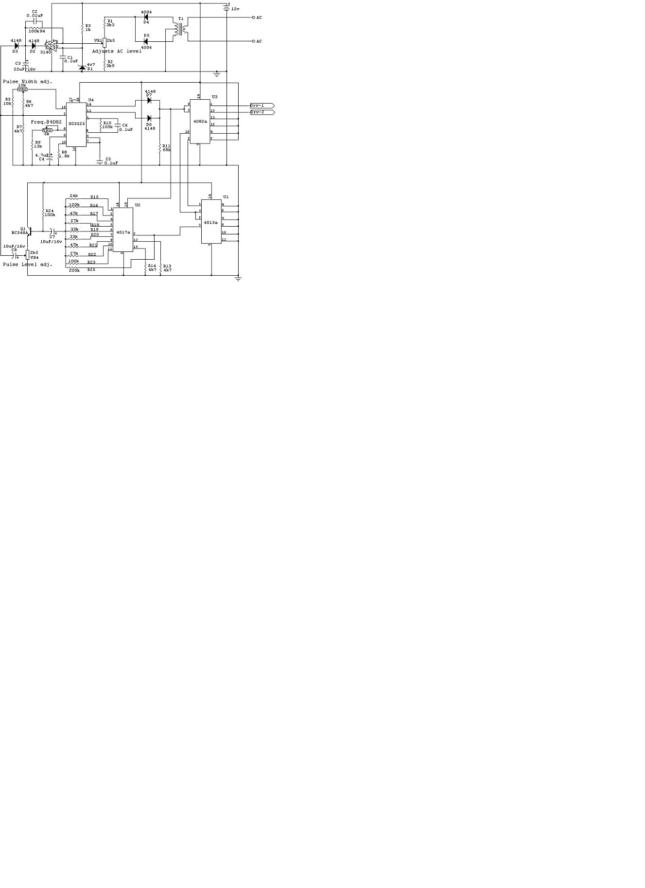
Inverter Schematic
«
on:
July 08, 2004, 07:45:41 AM »
Sorry! I've converted it into JPEG, so hopefully you can now view it. Some added info: The design is for 24v. There is a small-value choke/cap combination on the AC side to smooth out the steps into sinewave. (25pF cap, 120mH choke.)
Thanks!
«
Last Edit: July 08, 2004, 07:45:41 AM by (unknown)
»
Logged
Print
Pages: [
1
]
Go Up
« previous
next »
Fieldlines.com: The Otherpower discussion board
»
Homebrewed Electricity
»
Controls
(Moderator:
ghurd
) »
Inverter Schematic