Author Topic: Help needed from the 555 people!  (Read 1694 times)

0 Members and 1 Guest are viewing this topic.

BT Humble

  • Sr. Member
  • ****
  • Posts: 475
Help needed from the 555 people!
« on: May 11, 2005, 05:02:52 AM »
This morning the fancy fuel relay for my LPG-fuelled truck failed on me (it's done it once before, but some tapping and wiggling cured it).  I'll have a look for dry solder joints when I get home, but just in case that doesn't work can anyone suggest a 555 timer chip - based solution?


Here's what it looks like:


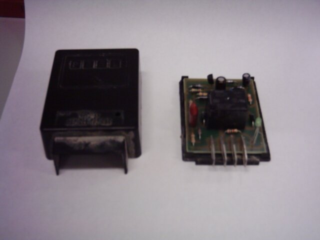
As you (might be able to) see it contains a relay, 2 transistors, 2 zener diodes, 5 rectifier diodes, 3 capacitors, 8 resistors and an LED.  I think that this is a little over-complicated.  ;-)


It has 4 terminals:


  1. Ignition coil negative;
  2. +12V (switched by the ignition key);
  3. +12V output to LPG tank valve;
  4. Chassis ground.


It needs to exhibit the following behaviour:


  • Low output from #3 if #2 is low;
  • Low output from #3 if more than ~3 seconds since a pulse was received from #1;
  • High output from #3 otherwise.


The LED should be lit if #3 is high, but that's so easy to work out that even I can manage it.  Can anyone help out with the rest?


I admit that I could just go to the shop and buy another one, but I could put that $45 to better use...


BTH

« Last Edit: May 11, 2005, 05:02:52 AM by (unknown) »

rotornuts

  • Hero Member
  • *****
  • Posts: 537
Re: Help needed from the 555 people!
« Reply #1 on: May 10, 2005, 11:53:14 PM »
I'm no genius with electronics but I often find that in automotive applications when there is a relay invoved it's the problem. The poor things take alot of use and the nickle plating on the contacts wears out. After the plating is worn out they pit badly and fail intermitently at first then completely. If you can pop the cap off the relay and examine the contacts that may be a good place to look first(unless that relay is solid state but it doesn't appear to be). It may still be contacting but with poor contact.
« Last Edit: May 10, 2005, 11:53:14 PM by (unknown) »

Trivo

  • Jr. Member
  • **
  • Posts: 66
Re: Help needed from the 555 people!
« Reply #2 on: May 11, 2005, 02:30:31 AM »
Hi BTH

Tried to fix the photo a bit for you


Trivo
« Last Edit: May 11, 2005, 02:30:31 AM by (unknown) »

commanda

  • Hero Member
  • *****
  • Posts: 731
Re: Help needed from the 555 people!
« Reply #3 on: May 11, 2005, 03:44:22 AM »
Second, after replacing the relay, re-solder the board; after replacing the capacitors. Second on the failure list after pitted relay contacts will be dried-out electrolytics from the heat. Get the more expensive 105 deg C types if you can.


Amanda

« Last Edit: May 11, 2005, 03:44:22 AM by (unknown) »

joelhacker

  • Newbie
  • *
  • Posts: 15
Re: Help needed from the 555 people!
« Reply #4 on: May 11, 2005, 10:05:34 AM »
You've got a good point...since the board is simple, you might be able to replace the failed component if you are steady with your soldering iron.  Also, I am always a little cautious anytime a relay is used to switch loads...watch the inductive kickback created by the coils and make sure that you have a diode across the coil to prevent inductive kickback into the controlling transistor (same principle of an ignition coil).  That will always cause premature failure of the unit...
« Last Edit: May 11, 2005, 10:05:34 AM by (unknown) »

BT Humble

  • Sr. Member
  • ****
  • Posts: 475
Re: Help needed from the 555 people!
« Reply #5 on: May 11, 2005, 04:15:20 PM »
Thanks to everyone for your suggestions.  As it turned out, re-soldering all the joints did the trick and I'm back in business again.


BTH

« Last Edit: May 11, 2005, 04:15:20 PM by (unknown) »

BT Humble

  • Sr. Member
  • ****
  • Posts: 475
Re: Help needed from the 555 people!
« Reply #6 on: May 16, 2005, 04:13:03 PM »
...and the problem was likely made worse by the ignition points closing up and leaving me with about 10 degrees of dwell rather than 52 degrees as the manual stipulates! ;-)


BTH

« Last Edit: May 16, 2005, 04:13:03 PM by (unknown) »

Bruce S

  • Administrator
  • Super Hero Member Plus
  • *****
  • Posts: 5376
  • Country: us
  • USA
Re: Help needed from the 555 people!
« Reply #7 on: June 21, 2005, 04:25:09 PM »
A little late seeing this, but I'd be interested in the LPG layout.

The unit looks like it belongs to the Fuel cut-off circuit. Is this a duel fuel truck setup?

I have an older F100 I'm looking to make duel OK tri-fuel As I am currently running it on Gas/Alky and would like to bring it up to LPG for it's cylinder cleaning ability's.

I know it's way off subject , but could you send specifics?


Cheers!!

Bruce

« Last Edit: June 21, 2005, 04:25:09 PM by (unknown) »
A kind word often goes unsaid BUT never goes unheard

BT Humble

  • Sr. Member
  • ****
  • Posts: 475
Re: Help needed from the 555 people!
« Reply #8 on: June 23, 2005, 04:30:17 PM »


A little late seeing this, but I'd be interested in the LPG layout.

The unit looks like it belongs to the Fuel cut-off circuit. Is this a duel fuel truck setup?

I have an older F100 I'm looking to make duel OK tri-fuel As I am currently running it on Gas/Alky and would like to bring it up to LPG for it's cylinder cleaning ability's.

I know it's way off subject , but could you send specifics?


Mine couldn't be simpler, it's fuelled by LPG only.  I briefly considered a dual fuel LPG/Petrol setup, but at the time:


(a) Petrol cost about AUD$1.00 per litre;

(b) LPG cost about AUD $0.35 per litre;

(c) Even though my truck only has a 2 litre engine, it weighs almost 2 tonnes when empty.  So I get about 6km/litre (14mpg);

(d) Dual fuel conversion would have cost more;

(e) I can tune the engine properly for LPG, rather than having a "compromise tune" to suit either fuel.


That circuit board is the "Ignition off and/or engine not running" fuel shut-off controller.  The electromechanical valve itself is installed at the tank.


BTH

« Last Edit: June 23, 2005, 04:30:17 PM by (unknown) »