Author Topic: Over 90% Converter.  (Read 8270 times)

0 Members and 1 Guest are viewing this topic.

QUAZ HOLT

  • Jr. Member
  • **
  • Posts: 72
Over 90% Converter.
« on: April 24, 2006, 07:15:37 PM »
This is it!

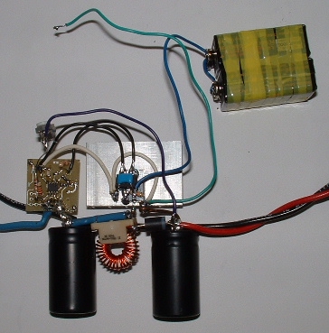
Hand wired unit built yesterday after tea.

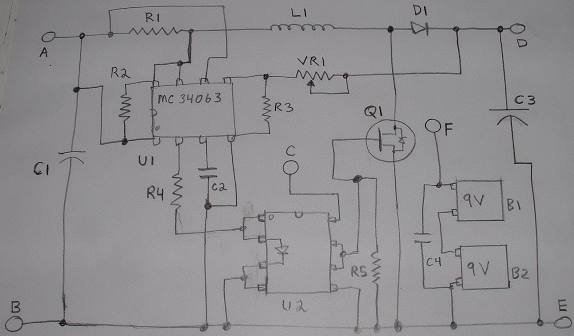
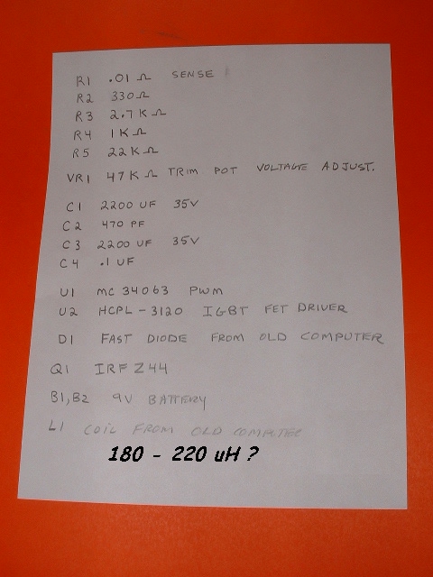
Circuit diagram of converter. Coil, Fet IRFZ44, Fast Diode, PWM MC34063 and frequency capacitor from old pentium 75 motherboard.

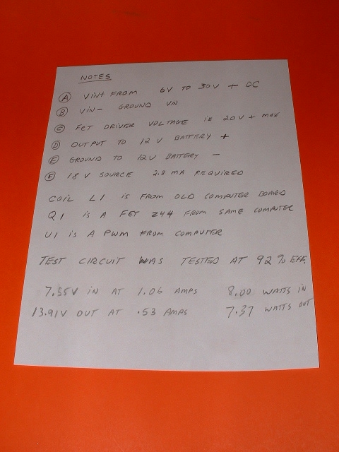
The IGBT Fet driver (HCPL-3120) is very important in this design. It has a low voltage lockout, opto coupled input and can run up to 10 Mhz. The two 9v batteries supply the 18 volt power to drive the 50 amp fet hard. 3 ma is the drain on the 18volt supply. This can be changed to a 18 volt micro power step up inverter. (Dinner was calling) Fast and dirty way to get the fet drive voltage.The sense resistor limits the input current and can be changed to increase the power. Needs more testing. Tested to 10 amps 6 volts in. We need more power, Scotty.

Lexmark ink jet printers also have some use. It contains some of the same parts. I can gut one in 10 - 1/2 seconds. Bill.
« Last Edit: April 24, 2006, 07:15:37 PM by (unknown) »

wooferhound

  • SuperHero Member
  • ******
  • Posts: 2288
  • Country: us
  • Huntsville Alabama U.S.A.
    • Woofer Hound Sound & Lighting Rentals
Re: Over 90% Converter.
« Reply #1 on: April 24, 2006, 02:53:34 PM »
What does it do ?

« Last Edit: April 24, 2006, 02:53:34 PM by (unknown) »

oztules

  • Hero Member
  • *****
  • Posts: 1477
  • Country: aq
  • Village idiot
Re: Over 90% Converter.
« Reply #2 on: April 24, 2006, 03:18:59 PM »
Nicely done.  Hope to see more on this as tests get more powerful. R1 has taken some of the excitement out of it though:-)
« Last Edit: April 24, 2006, 03:18:59 PM by (unknown) »
Flinders Island Australia

dinges

  • Hero Member
  • *****
  • Posts: 1294
  • Country: nl
Re: Over 90% Converter.
« Reply #3 on: April 24, 2006, 03:38:55 PM »
Depending on your electronics abilities, it either doubles voltage (7-->14V @ ??A max?) or throws debris, sparks and smoke in your face. See other post by Oztules.


Curious as to max. current and whether the 13.91V is stabilized. I can't remember ever having seen that U2 before. The rest seems pretty conventional, though it's still in the prototyping stage, from the looks of it.


Peter.

« Last Edit: April 24, 2006, 03:38:55 PM by (unknown) »
“Research is what I'm doing when I don't know what I'm doing.” (W. von Braun)

Slingshot

  • Full Member
  • ***
  • Posts: 231
Re: Over 90% Converter.
« Reply #4 on: April 24, 2006, 04:11:25 PM »
Your notes say input is 6V to 30V, but the schematic appears to be a boost-only.  How does this circuit regulate 30 volts down to 12?
« Last Edit: April 24, 2006, 04:11:25 PM by (unknown) »

georgeodjungle

  • Full Member
  • ***
  • Posts: 193
Re: Over 90% Converter.
« Reply #5 on: April 24, 2006, 05:05:47 PM »
nicely done.

we can figure out that choke.

just need some stats about it.
« Last Edit: April 24, 2006, 05:05:47 PM by (unknown) »

QUAZ HOLT

  • Jr. Member
  • **
  • Posts: 72
Re: Over 90% Converter.
« Reply #6 on: April 24, 2006, 06:20:26 PM »
I have a meter that can measure coils and I am removing the coils from computers and old inkjet printers. The coil is measured and the frequency capacitor is also measured. This is the simple way to do the math. 330 uh coil with a 330 pf cap . is one from an old lexmark printer. Other than that you can take a guess. The circuit is a step up converter and when the voltage exceeds the set voltage ie.(13.76v) the power travels right through the coil and diode and into the battery. The circuit can have 30v dc input without smoke. The battery works as a shunt when less then 13.76 volt. The genny I am working with will put out 15 volts at 1900 rpm and this condition is when there is a very good wind storm. Bill.
« Last Edit: April 24, 2006, 06:20:26 PM by (unknown) »

QUAZ HOLT

  • Jr. Member
  • **
  • Posts: 72
Re: Over 90% Converter.
« Reply #7 on: April 24, 2006, 06:45:49 PM »
The circuit u2 is a very good fet driver and allows fast speed switching with opto coupled isolation. The IGBT driver is a (Hewlett Packard hcpl 3120). This helps in proto type stages to avoid slow turn on and low voltage fet drive problems. To turn a fet on fast you need 20 volts and this chip has all the right stuff to do the job. The voltage of the PWM (MC34063) can be set by the trimmer resistor and this circuit used a single turn pot, a little hard to adjust exactly. Will add pad resistors or a 20 turn pot and make range 13 to 14 volts. Higher voltage will charge the batteries faster and should be reduced when battery is 80% charged or there about. A relay could switch the output to a different bank when the first bank is charged. A dream "all my batteries charged fully by wind and solar". Bill.
« Last Edit: April 24, 2006, 06:45:49 PM by (unknown) »

RP

  • Hero Member
  • *****
  • Posts: 722
  • A dog with novelty teeth. What could go wrong?
Re: Over 90% Converter.
« Reply #8 on: April 24, 2006, 10:40:19 PM »
I hate to be picky but in your efficiency calculations, did you take into account the energy supplied by the 9 volt batteries?  Also have you measured the current draw on them when running at frequency?
« Last Edit: April 24, 2006, 10:40:19 PM by (unknown) »

Opera House

  • Sr. Member
  • ****
  • Posts: 261
Re: Over 90% Converter.
« Reply #9 on: April 25, 2006, 06:44:25 AM »
That will teach him!  Don't post anything here that isn't built using a hammer.  I'm wondering if some of those spikes aren't getting into your meter.  I wouldn't expect you could get over 88-89% with this circuit.  How did you come up with using a 34063? www.siliconchip.com has another version of this 34063 circuit without the driver if people want some more technical details.  Nice to see an old switcher and new driver can live in harmony.
« Last Edit: April 25, 2006, 06:44:25 AM by (unknown) »