Author Topic: Circuit to harvest Turbine power with Resistive loads  (Read 1605 times)

0 Members and 1 Guest are viewing this topic.

CompDoc

  • Newbie
  • *
  • Posts: 8
Circuit to harvest Turbine power with Resistive loads
« on: January 16, 2007, 07:33:06 PM »
Active Load DC heater control for common 9/12 with logical-hysteresis using picAxe08M.

------------------------------------------------------------------------------------

This controller was designed with, and put into production on, my PicAXE-ProjectBoard previously posted.  The project board accommodates the direct replacement of the three output transistors with N-Mosfets (T220 case) required to switch multiple elements/loads at higher power levels with minimum losses.  Also, to facilitate Blade-RPM reduction when load is increased, a hysteresis of +/-50RPM is built into the controller-logic. (Refer to the Axe08M Project Board diagrams in my files for additional information.)


The controller continually monitors turbine RPM(pin3) and actively adjusts the load on the alternator at different speeds.   Because every turbine has different power generating characteristics, a manual method of tuning/adjusting RPM to load is required. This was achieved with the high resolution analog to digital (10-bit ADC) input of AXE08M, which conveniently gives a 0-255 step reference to instruct the controller when to start applying the loads. On the controller, conversion of an analog input from a potentiometer, spanning the circuits supply rails, provides this adjustment which is used to set the load engagements points for efficient harvesting of turbine power.


This manual adjustment will result in an actively increasing "load" window starting with 150-300rpm (for larger machines) sequentially in 25 steps toward 400-550rpm for smaller machines.  With proper adjustment, the controller will maintain `over-speed' control, and tames the turbine while tracking maximum power for heat generation.  As always, a properly adjusted furling system is required, and necessary, for winds driving the turbine beyond this control-window.  Transmission line loses should be considered.


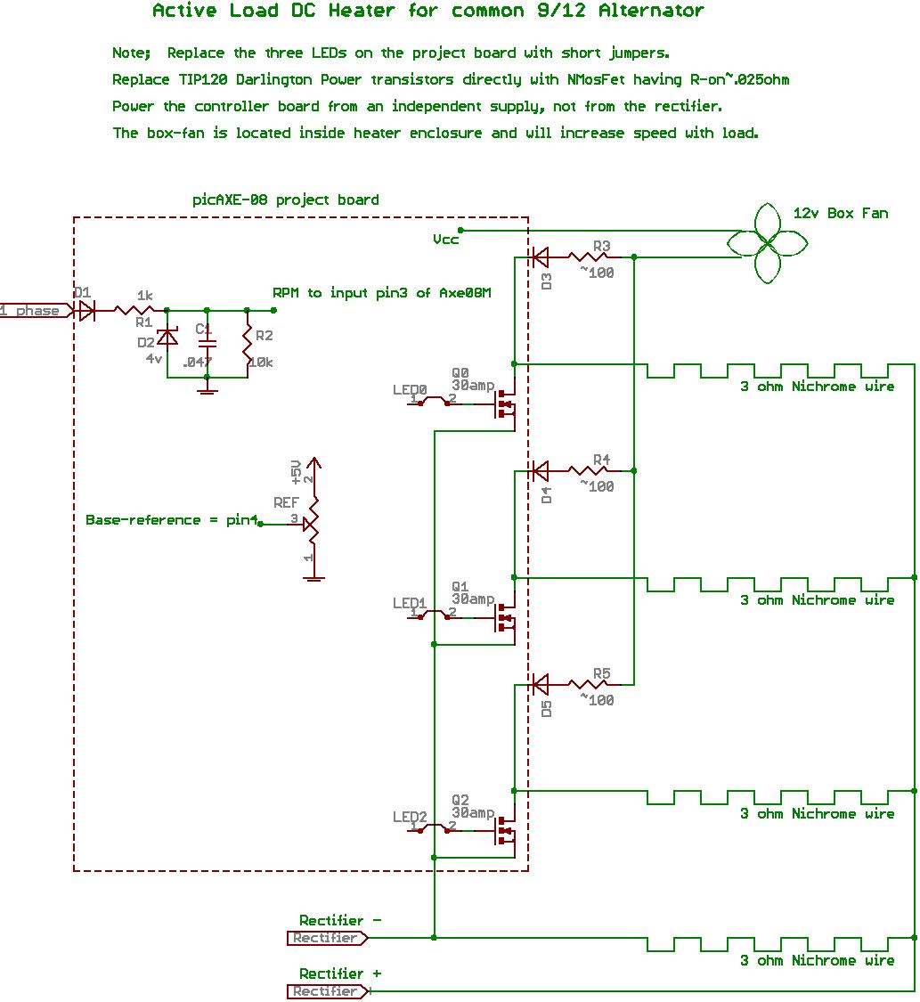
The prototype includes four heater elements, each made from 3ohms of Nichrome wire salvaged from spent dryer elements.  Note; different resistive loads, and combinations of, may result in more efficient harvesting of power, however, do not exceed "total-equivalent parallel resistance" less than that of the alternators single-phase resistance.  This controller was not designed to run directly from the battery-bank, but as a diversion of power after batteries are charged or as a completely independent variable heat source.


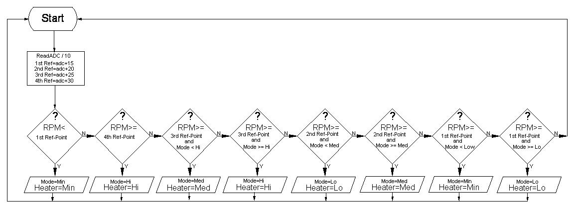
You will fine the controllers AXE-code(basic) in my files, which is heavily commented and should be self explanatory, even for the novice programmer.

The following is a logical flow chart of the program for clarity.  (You may have to print this image for legibility.)


Comments and questions are welcome.

Doc.


Moved to the proper section.


« Last Edit: January 16, 2007, 07:33:06 PM by (unknown) »

commanda

  • Hero Member
  • *****
  • Posts: 731
Re: Circuit to harvest Turbine power with Resistiv
« Reply #1 on: January 16, 2007, 01:42:19 PM »
Just on the hardware;


10 bit ADC should give 0 - 1023.

Mosfets should be logic-level gate types.


Amanda

« Last Edit: January 16, 2007, 01:42:19 PM by (unknown) »

willib

  • SuperHero Member
  • ******
  • Posts: 2414
  • Country: us
Re: Circuit to harvest Turbine power
« Reply #2 on: January 16, 2007, 03:01:32 PM »
Hi Compdoc,

i commend your work

are you  trying to drive the Fet gates with the collectors of your TIP120 BJT's alone ? Or from the LED outputs?

if you are using the BJT's then

add a suitable resistor from each collector to the positive rail, to  pull up the voltage and connect the gate between the resistor and collector ,you might have to change the program ,because when the LED is on the BJT will be on and the Fet will be off , unless i missed what the BJT's were for?
« Last Edit: January 16, 2007, 03:01:32 PM by (unknown) »
Carpe Ventum (Seize the Wind)

CompDoc

  • Newbie
  • *
  • Posts: 8
Re: Circuit to harvest Turbine power with Resistiv
« Reply #3 on: January 16, 2007, 05:28:42 PM »
Good eye, Amanda, 10 bits will give 1024 steps, however, for picAxe with 10 bit ADC types, the reading will be rounded to a byte value 8 bits long.  Sorry for any confusion.

Yes, the N-Mosfets should be chosen with a full-On state voltage of 4 volts. Also, the current rating should be applicable to the expected maximum power of the mill, and the full-on resistance should be as small as possible to minimize thermal overload of the fets.
« Last Edit: January 16, 2007, 05:28:42 PM by (unknown) »

commanda

  • Hero Member
  • *****
  • Posts: 731
Re: Circuit to harvest Turbine power
« Reply #4 on: January 16, 2007, 05:31:40 PM »
Quoting CompDoc;


The project board accommodates the direct replacement of the three output transistors with N-Mosfets (T220 case)


Amanda

« Last Edit: January 16, 2007, 05:31:40 PM by (unknown) »

CompDoc

  • Newbie
  • *
  • Posts: 8
Re: Circuit to harvest Turbine power
« Reply #5 on: January 16, 2007, 05:38:24 PM »
Thanks, willib.  No, the Axe can drive the logic-level fets directly. Simply replace the TIP120 NPNs with the fets, most fets(T220 case) are pin for pin compatable. Replace the LEDs with a short jumper.  This is because no real current flows thru the gate of a Mosfet, so the LEDs on the project board are useless here. Note, the circulating fan and components are optional, and you may need to adjust the three-R values, depending on the fan used, for maximum air-flow at HIGH range.
« Last Edit: January 16, 2007, 05:38:24 PM by (unknown) »

electronbaby

  • Sr. Member
  • ****
  • Posts: 407
  • Country: us
    • Windsine.org
Re:Turbine power with Resistive loads
« Reply #6 on: January 16, 2007, 08:58:44 PM »
Hello CompDoc,


Are you trying to convert the harvested power into heat?.. or are you simply trying to create a dump load that can adjust its wattage handling capability automatically? This is probably for an off grid / stand alone system. If you dont need the power, wouldnt it be wiser to just shut down the turbine automatically when not needed? Or better yet, if you didnt want to completely shut it down, you could design a circuit to measure frequency of the output ac waveform and use it to fire fets to dump the excess power based on either frequency or amplitude (after the rectifier). the fets would fire into the resistors bases on the amplitude of the turbine output. This would allow you to easily cap the output but still have an easy adjustment, without a microcontroller. Ive been using a huge set of IGBT's after the rectifier (protected by a blocking diode to be able to short out the turbine when not needed (solid state).  no failures yet. lol


just some constructive criticism :-P

cool design.

good luck :-)


RoyR

« Last Edit: January 16, 2007, 08:58:44 PM by (unknown) »
Have Fun!!!  RoyR KB2UHF

CompDoc

  • Newbie
  • *
  • Posts: 8
Turbine power with Resistive loads
« Reply #7 on: January 17, 2007, 05:32:59 AM »
No, Roy, this post is for sharing a good method of harvesting energy as heat, without the over-speed issues seen when using resistive loads. i.e. resistance increases with heat, which in-turn, results in less of a load and the mill "runs wild".  Also, this controller 'tracks' the maximum power, at any given second, that the turbine is producing, and produces a good usable source of heat.  With the proper element (resistance) combination, maximum efficiency is achieved.

« Last Edit: January 17, 2007, 05:32:59 AM by (unknown) »

CompDoc

  • Newbie
  • *
  • Posts: 8
Re: Circuit to harvest Turbine power with Resistiv
« Reply #8 on: January 17, 2007, 06:55:09 AM »
Update;  Amanda, the information I posted re the 10-bit ADC in the Axe system is incorrect.  The high resolution analog to digital(ADC 10-bit) input of AXE08M conveniently gives a '0-1023' step conversion of a analog potentiometer spanning the controllers supply rails.  The Axe-documentation is fuzzy on explaining this.


After testing/verifying this, I have adjusted my routine and re-posted in my files.  The end result is still applicable to my description/post.  i.e. 25 increments of adjustment.

Thank you!

« Last Edit: January 17, 2007, 06:55:09 AM by (unknown) »