Author Topic: Best way to Dump?  (Read 6171 times)

0 Members and 1 Guest are viewing this topic.

Shadow

  • Sr. Member
  • ****
  • Posts: 473
Best way to Dump?
« on: January 27, 2007, 02:50:44 PM »
I plan on using a 100 gallon glass lined water tank as a dump for my wind turbines. I have two wind turbines,48 volt may need to dump up to 30 amps ? each. I have a Morningstar, TS-60 that will control the diversion.


         I have purchased 2 48 volt DC elements that can draw 20 amps each,and one 120 volt (AC) 1500 watt element,First is this going to be enough dump? I think I have room for one more elemnt and could replace one 48 volt with another 1500 watt.


        Second, Whats the best way to configure these, it would be nice to have them come on in sequence as needed rather than all at once.

        Third, Is the TS-60 big enough to handle this or  do I need two? I have considered using 1 TS-60 to sense battery voltage and dump to the two 48 volt elements, then maybe a second TS-60 or TS-40 to sense the current of the two DC elements and when they reach their capacity it would dump to the 1500 watt element? Could this be made to work?

          And finally fourth, What size wire should I be looking at to run the 50 feet from the battery house to the water tank in the basement?

              Thanks for any and all suggestions.

« Last Edit: January 27, 2007, 02:50:44 PM by (unknown) »

Birdmanjack

  • Newbie
  • *
  • Posts: 11
Re: Best way to have a Dump?
« Reply #1 on: January 27, 2007, 07:59:51 AM »
I just used the 1500 240 volt elements already in the hot water tank I obtained. Why pay for special elements when the originals work just fine. Lets the turbine start with no problems and you don't need to keep adding elements. It will use as much element heat wise as it needs and it does not care if it is ac or dc. Just my thoughts on what you are doing.
« Last Edit: January 27, 2007, 07:59:51 AM by (unknown) »

Shadow

  • Sr. Member
  • ****
  • Posts: 473
Re: Best way to have a Dump?
« Reply #2 on: January 27, 2007, 08:12:50 AM »
I'm not sure what this tank was originally used for, it had no elements in when I got it. I purchased these elements about a year ago and would like to use them if I could but maybe I'd be better off using all 120/1500 watt elements instead of any 48 volt ones? We'll see what others say.
« Last Edit: January 27, 2007, 08:12:50 AM by (unknown) »

Flux

  • Super Hero Member Plus
  • *******
  • Posts: 6275
Re: Best way to have a Dump?
« Reply #3 on: January 27, 2007, 09:01:08 AM »
Your 120V heater will load at about 375W on half volts, that is about 7.5A.


You will be short of your 60A but if you have other loads then it may be enough.


If you have to buy more heaters then you have to balance needing more standard units against one more expensive special.


I know nothing about the Morningstar controller but I assume it dumps as Pwm so you can connect all the heaters in parallel up to 60A and it will dump in proportion to the excess power.


Flux

« Last Edit: January 27, 2007, 09:01:08 AM by (unknown) »

Flux

  • Super Hero Member Plus
  • *******
  • Posts: 6275
Re: Best way to have a Dump?
« Reply #4 on: January 27, 2007, 09:12:18 AM »
Just one more thought, if those heaters have thermostats, make sure they are set so high that they don't operate, they will not break 50dc.

Flux
« Last Edit: January 27, 2007, 09:12:18 AM by (unknown) »

SamoaPower

  • Sr. Member
  • ****
  • Posts: 417
Re: Best way to Dump?
« Reply #5 on: January 27, 2007, 09:56:58 AM »
First.

You're confusing the issue by using different load specifications. It's easiest to understand by reducing the load specs to their equivilent resistances. Your 48V loads are 2.4 ohms each. The 120V load is 9.6 ohms. The three in parallel is 1.07 ohms. The current at 53V (battery float voltage) is 49.5A.


What you need to divert 60A is .88 ohms. Adding another 120V element gets you down to .96 ohms, still not low enough. Better would be a third 48V element. Three in parallel would give you .8 ohms.


By the way, your 1500W, 120V element will only dissipate about 300W at 53V.


Second.

I believe your controller is a PWM type in diversion mode, so the load is already applied in a variable, progressive fashion. There's no need or advantage to sequencing the loads.


Third.

This issue has come up on other posts. It's easy to forget that the primary job of a diversion controller is to charge the battery with an acceptable algorithm. Protecting the mills is a secondary job.


Connecting controllers in parallel, whether using separate loads or not, will screw up the battery charge algorithm. I wouldn't recommend doing it.


Fourth.

#6 wire will give less than a 5% voltage drop.

« Last Edit: January 27, 2007, 09:56:58 AM by (unknown) »

SamoaPower

  • Sr. Member
  • ****
  • Posts: 417
Re: Best way to have a Dump?
« Reply #6 on: January 27, 2007, 12:57:42 PM »
Birdmanjack,


I hope you're not thinking you have a 3000W load with those two 1500W 240V elements.


In a 48V system they will dissipate about 146W.

In a 24V system they will dissipate about 37W.

In a 12V system they will dissipate about 9W.


Yes, I'm sure the turbine does start easily since it has a very light load but I bet you don't get much hot water.


I suggest you change your loads before you get a big wind.

« Last Edit: January 27, 2007, 12:57:42 PM by (unknown) »

Shadow

  • Sr. Member
  • ****
  • Posts: 473
Re: Best way to Dump?
« Reply #7 on: January 28, 2007, 08:06:42 AM »
Thanks for the comments;

             I'll probably order another one or 2 48 volt elements. I'm still confused on the wiring configuration. These posts indicate wiring them in parralell, but the web page where I got the elements suggest wiring in series.


            I realize individual elements are wired in series, to get 48 volt, but I read it as second elements should be in series too.Maybe I'm reading wrong.


         http://store.altenergystore.com/FusesBreakersEtc/Dump-Loads-Dump-Load-Controllers/Diversion-LoadsDum
p-Loads/Low-Voltage-Water-Heating-Element-2448V/p2327/


« Last Edit: January 28, 2007, 08:06:42 AM by (unknown) »

Flux

  • Super Hero Member Plus
  • *******
  • Posts: 6275
Re: Best way to Dump?
« Reply #8 on: January 28, 2007, 08:44:05 AM »
Each unit consists of two 24v heaters.


At 24v you can use them individually or in parallel, but at 48V you must use both in series giving 1.92 ohms.  Regard it as one heater of 1.92 ohms.


At float volts this will take about 27A, so your two in parallel should dump about 56A

using their figures.


The 120v 1500W unit will add another 6 or 7A so that would give your 60A that you want.(It is likely that you would not even need the 120v heater)


You connect each individual unit in parallel. The series bit only applies to the permanent connection between the 2 parts of a device.


Flux

« Last Edit: January 28, 2007, 08:44:05 AM by (unknown) »

Shadow

  • Sr. Member
  • ****
  • Posts: 473
Re: Best way to Dump?
« Reply #9 on: January 28, 2007, 12:22:19 PM »
Perfect, Thanks Flux.. Always like to be sure before wiring it wrong. I'm finding with electrical things you dont always get a second chance.
« Last Edit: January 28, 2007, 12:22:19 PM by (unknown) »

(unknown)

  • Guest
Re: Best way to Dump?
« Reply #10 on: February 11, 2007, 03:19:10 PM »
I have a situation similar to Shadow's. I'm diverting mostly hydro - about 900 watts at nominal 48v - to two 48v water heater elements with a 60 amp tri-star (when the sun shines, the tri-star also diverts excess PV power so I sometimes see 30+ amps going to hot water). The system works fine except for the fact that the ac thermostats are useless. Thus, the tank occasionally overheats.


Any thoughts on dumping excess power via 120v ac? That way, I could use two 220v elements rated at say, 4500 watts, and the factory thermostats would actually work.

« Last Edit: February 11, 2007, 03:19:10 PM by (unknown) »

RP

  • Hero Member
  • *****
  • Posts: 722
  • A dog with novelty teeth. What could go wrong?
Re: Best way to Dump?
« Reply #11 on: February 11, 2007, 06:18:47 PM »
I'm not sure you want those thermostats to work anyway (at least not the normal way).  If the thermostat opens then you won't have a dump load anymore.  It seems like you need a way to switch to an alternative dump load when the water is hot.  A few thoughts:


Can you get at the water heater heat element thermostats and use them to trigger an external relay to switch the load to a nicrome air heater for instance?  


Another option would be to add an external temperature sensor to do the same thing.  One good way would be the adjustable thermostats used for the blower in a gas or oil furnace.  These switch on the blower motor after the heat exchanger is up to 135-150°F or so.  The probe part could be tucked under the water tank insulation and against the tank.

« Last Edit: February 11, 2007, 06:18:47 PM by (unknown) »

(unknown)

  • Guest
Re: Best way to Dump?
« Reply #12 on: February 12, 2007, 09:54:40 AM »
Thanks RP. I have a second dump load, an air heater, that's controlled by the auxiliary function on my inverter. It kicks in when the temperature limiting switch on the top thermostat cuts off power to both elements. This happens when water at the top of the tank is about 170 degrees. It's the only function of the two thermostats that actually works. That switch has to be manually reset - in our case about once a day once we've taken a bath or a couple showers.


I'd like to have the thermostats work sequentially, as designed, so that as the top of the tank comes up to set temp the bottom element activates. As it is now, the two elements are on together - water is very hot at the top and lukewarm at the bottom.


The external temperature sensors sounds like they might work to bypass the thermostats. In my case, I guess they'd switch off power. I don't quite see how the existing thermostats could be used to activate a relay, though. Would that mean energizing them with a separate 120v circuit?

« Last Edit: February 12, 2007, 09:54:40 AM by (unknown) »

RP

  • Hero Member
  • *****
  • Posts: 722
  • A dog with novelty teeth. What could go wrong?
Re: Best way to Dump?
« Reply #13 on: February 12, 2007, 07:09:35 PM »
As for the existing heat element thermostats:  I don't know how they're set up but I was hoping you could get at the electrical connections to the thermostat itself (seperate from the heat element).  Perhaps with a little surgery?  If so, you could use the thermostats to turn on relays that could handle the 48VDC current.  


That way you could have the top thermostat divert the power to the bottom element when the top is hot.  When the bottom gets hot also then the bottom thermostat would switch the power to an external load (like your air heater).


Using an external thermostat would work similarly.  When the tank is hot, the thermostat turns on a relay to divert power to an external load instead of the heat elements.


I hope this is helping.  If I'm not being clear just let me know...

« Last Edit: February 12, 2007, 07:09:35 PM by (unknown) »

(unknown)

  • Guest
Re: Best way to Dump?
« Reply #14 on: February 19, 2007, 03:40:08 PM »
The connections on the thermostats are easy to get to. Any thoughts on the type of relay to use? And if you have it in mind, a brief description of the wiring involved would be much appreciated.


Thanks again.

« Last Edit: February 19, 2007, 03:40:08 PM by (unknown) »

RP

  • Hero Member
  • *****
  • Posts: 722
  • A dog with novelty teeth. What could go wrong?
Re: Best way to Dump?
« Reply #15 on: February 19, 2007, 10:40:36 PM »
It would help if you could give a little more info on the 48v heater elements.  Do you have a part number or a photo?  Also, do they have 4 terminals (two for the heater and two for the thermostat) each or less than 4?
« Last Edit: February 19, 2007, 10:40:36 PM by (unknown) »

(unknown)

  • Guest
Re: Best way to Dump?
« Reply #16 on: February 22, 2007, 03:18:28 PM »
Rather than try to describe the wiring configuration on the thermostats, or God forbid, attempt a digital drawing, here's a link to the manual:  


http://waterheating.rheem.com/Documents/ResourceLibrary/UseAndCare/RheemResElec/AP9029.pdf  


It's not a very large file - took me about two minutes on a very slow connection to download. My setup is illustrated on page 20, Fig. D.


Each water heater element consists of two 24 volt, 22 amp elements that are wired in series, with the use of a jumper, to draw 22 amps at 48 volts. Thus, there are four terminals for each element with the jumper across two of the terminals and diversion negative and positive leads to the other two.

« Last Edit: February 22, 2007, 03:18:28 PM by (unknown) »

RP

  • Hero Member
  • *****
  • Posts: 722
  • A dog with novelty teeth. What could go wrong?
Re: Best way to Dump?
« Reply #17 on: February 22, 2007, 07:53:06 PM »
Okay, here's how I'd do it (appologies for the butchered image)


The red wire is the heavy stuff you use to connect to the heater elements.  The green wire is 20 gauge or so.  All it does is power the relay coils.  The relays should have contacts rated for at least 48volt DC and it would be a little simpler if the coils are rated for 48 volts also but you can use lower voltage coils with series resistors if needed.


How it works:


The thermostats now control the relay coils.  When everything is cold, the upper thermostat is on and delivering power through the green wire to the upper relay coil.  This causes current to be conducted to the normally open contact of the relay which delivers power through the red wire to the upper heat element.


When the top of the tank gets warm, the upper thermostat turns off which de-energizes the upper relay.  Now power is diverted to the normaly closed contacts of that relay to the wiper of the lower relay.  The upper heat element is now off.


Since the lower thermostat is still cold, it is conducting power to the coil of the lower relay and turns it on so that the red wire connected to the normally open contact is energized and the lower heater is now on.


If the upper part of the tank cools off then the upper relay will switch on again and power switches back to the upper heat element.


If both the upper and lower thermostats register as warm then all power is diverted to an external air-heater or another relay.


The way it's shown here, if the manual reset over-temp trips, all power goes to the external air-heater.


I think all you'll need to obtain is 2 relays and some wiring supplies.


Hope this helps...

« Last Edit: February 22, 2007, 07:53:06 PM by (unknown) »

ghurd

  • Moderator
  • Super Hero Member Plus
  • *****
  • Posts: 8059
Re: Best way to Dump?
« Reply #18 on: February 23, 2007, 06:59:43 AM »
Someone should point out that circuit will have only have 1 element heating at a time.

One 22A element will be about 10A short of the 30+A Josh needs to dump.


My first idea looking at this would be each relay feeding its own, separate, 18~20A dump load when in the de energized state.


But that does not address the high frequency switching of the TriStar.  The relays will be buzzing and kill the contacts in short order.


Maybe the relays can be removed from the system, if the thermostats contacts can handle the DC amps.  

It could be done using pin #4 on the thermostat's contacts.

The contacts should have an arc suppression circuit (I think), like a properly sized cap across them.   It may not be much of an issue because the thermostat contacts will not be switching often.


G-

« Last Edit: February 23, 2007, 06:59:43 AM by (unknown) »
www.ghurd.info<<<-----Information on my Controller

ghurd

  • Moderator
  • Super Hero Member Plus
  • *****
  • Posts: 8059
Re: Best way to Dump?
« Reply #19 on: February 23, 2007, 07:17:19 AM »
Also, the TriStar may not appreciate being connected to relays, unless reverse diodes are connected across the coils.
« Last Edit: February 23, 2007, 07:17:19 AM by (unknown) »
www.ghurd.info<<<-----Information on my Controller

RP

  • Hero Member
  • *****
  • Posts: 722
  • A dog with novelty teeth. What could go wrong?
Re: Best way to Dump?
« Reply #20 on: February 23, 2007, 05:15:58 PM »
Good points,  I forgot this was to be driven PWM from a controller.  In that case the relays should be driven from a clean DC source rather than the incoming dumpload power as I drew it.


He said up above that he preferred to have the elements sequence rather than come on together and (I think) he said he needed to dump about 900 watts so 22amps at 48 volts would be a bit over 1kw.


I suspect the thermostats can't switch a 22 amp load which was why I suggested external relays.  

« Last Edit: February 23, 2007, 05:15:58 PM by (unknown) »

(unknown)

  • Guest
Re: Best way to Dump?
« Reply #21 on: February 23, 2007, 05:34:11 PM »
RP, I'm probably missing something, but it looks from your schematic like the upper and lower thermostat controls have been bypassed. The heat sensitive springs that trips back and forth between contact 2 and 4 on lower part of the upper thermostat and between contact 1 and 2 on the lower thermostat tell the elements when to come on and off. Without those in the loop, I can't see why the upper element wouldn't always be in the on position.


G, the maximum diversion at this point from my hydro is about 20 amps. I pick up more amps when the hydro and solar array are dumping together, at which point the heater element maxes out and the charge control on the solar side shuts down any excess power from the panels to the batteries. In any event, the heater elements are properly sized for the hydro which is what I care about.  


Anyway, I think you're right about the TriStar killing the contacts on the relays. As configured now, the thermostat contacts can handle dc - it's the heat sensitive springs that fuse to contact 2, upper and lower, such that the upper element (and lower if wired in series) are always energized.


So maybe back to square one - do you all think it would be feasible to substitute ac heater elements and use the connect/disconnect regulator - auxiliary function - on the inverter (instead of the PWM TriStar) through a relay to switch on and off ac power to the water heater?


Thanks for all the input.

« Last Edit: February 23, 2007, 05:34:11 PM by (unknown) »

RP

  • Hero Member
  • *****
  • Posts: 722
  • A dog with novelty teeth. What could go wrong?
Re: Best way to Dump?
« Reply #22 on: February 23, 2007, 11:47:41 PM »
No, the thermostats still function as you'd expect.  If I read the schematic correctly both thermostats will have contacts #1 and #2 connected when the thermostat is cold (normally closed).  Starting with the upper thermostat:


Power is conducted from the max over temp switch to contact #1 of the thermostat and through it to #2 (when cold).  The green wire carries this to the upper relay coil and energizes it.  This causes the wire of the upper relay to pull down to the lower contact which essentially switches on the upper heat element.


When the upper thermostat gets hot the wiper will switch from contact 2 to 4 leaving contact #2 unpowered.  WIth no power to its coil the upper relay turns off which allows its wiper to flip back to the top contact (normally closed).  At this point the upper heat element is off and all power is diverted to the lower relay wiper.


The bottom relay and thermostat work the same way except when it gets hot down there, power is diverted out to an external load.


The relays do the same thing as the thermostat contacts but can have heavier contacts and they are "commanded" to switch by the thermostats so you still have temperature control.  Your car has the same thing to operate the starter motor for the engine.  That's how you can switch on a 300 amp motor using the tiny contacts in the keyswitch assembly.


The issue of having PWM power and it's effect on the relay contacts can be solved in a couple different ways.  A simple filter consisting of a resistor and a capacitor could be connected to each relay coil or they could be powered by the battery bank by moving the green wires around a little.  If you'd like I can redraw the schematic to address this.

« Last Edit: February 23, 2007, 11:47:41 PM by (unknown) »

(unknown)

  • Guest
Re: Best way to Dump?
« Reply #23 on: February 24, 2007, 07:50:03 PM »
RP, I think I get it. What happened is that only the red wire shows on the schematic that you posted. Is there some way that you could re-post the drawing with all wiring shown in red? Then I think it should make sense.


Thanks again.  

« Last Edit: February 24, 2007, 07:50:03 PM by (unknown) »

RP

  • Hero Member
  • *****
  • Posts: 722
  • A dog with novelty teeth. What could go wrong?
Re: Best way to Dump?
« Reply #24 on: February 24, 2007, 09:04:28 PM »
Sorry about the bad picture.  I converted it to a gif to make for a compact file.  It must've compacted it by making it unusable.  Here it is as a jpeg file and I traced all the green wires with blue.  Hopefully it shows up better now.  It may help to save the image to your computer and view it in another program.


Hopefully with this version you can see how the thermostats control the relays to redirect power as needed.


This is the same diagram as above so the comments about changes for PWM etc. still apply (I didn't update the diagram to reflect those).


« Last Edit: February 24, 2007, 09:04:28 PM by (unknown) »

ghurd

  • Moderator
  • Super Hero Member Plus
  • *****
  • Posts: 8059
Pulsed 360hz DC and AC Contacts?
« Reply #25 on: February 24, 2007, 11:38:36 PM »
Not sure what is meant by "feasible to substitute ac heater elements and use the connect/disconnect regulator - auxiliary function - on the inverter", but I don't like the sound of it.


How many watts did the heater start out?

The PDF lists for fuses up to 50A, so a bit under 25A per element.  

I used to do a lot of handyman stuff and don't recall ever finding bad contacts in a water heater. They must be fairly heavy duty.


New thought, not sure if it's a good thought.

The TS-60 is PWM and every Morningstar unit I ever tested Hz on, came out to 356~359Hz. That should take care of the arcing?

The PWM could hit 100% duty cycle only if the dump load takes less power than the hydro is making. It is not. So the duty cycle should stay below 100%.


So maybe, just maybe, for this project, fast switching DC could be thought of as AC?


Meaning maybe the factory heater thermostats could be connected direct to the TS-60?

(Water heater manual, page 20, Fig B for Shadow, Fig D for Josh)


The upper thermostat has that pin #4 they only show a few times.

Does the lower thermostat also have a pin #4?

That would allow the air heater to be connected to pin #4.  Otherwise, there still needs to be a way to connect the air heater when the water is hot, and all the low contacts are open.


G-

« Last Edit: February 24, 2007, 11:38:36 PM by (unknown) »
www.ghurd.info<<<-----Information on my Controller

(unknown)

  • Guest
Re: Pulsed 360hz DC and AC Contacts?
« Reply #26 on: February 25, 2007, 03:37:17 PM »
RP, thanks for the diagram - I see what's happening.


The factory thermostats (and I'm on my second set), designed for ac current, don't work with my system because the "toggle" springs hinged at contacts 1 on the upper and lower thermostats tend to get welded shut to contacts 2 when passing dc current. It seems as though that would still occur with relays in the system because the springs and contacts are still passing dc current to the coils - if that makes sense.


As far as ghurd's comment about the feasibility of using ac water heater elements, my inverter, an Outback, like the Trace inverters, has an auxiliary function that when activated provides 12 vdc, 0.7 amp output. It can be programmed to perform various functions. Because I have a 48 vdc system, in this situation, it would be set to activate at about 54 vdc - that's float stage for my battery bank. In this "diversion" mode there is a programmable off delay - one to four minutes - which is the amount of time the auxiliary output is energized after voltage falls below the set point - 54 vdc.


My thought was forget about the TriStar as a diversion devise and to connect the aux output of the Outback to the coil of a relay which when energized would switch on ac current running through the relay contacts to the water heater thermostats. Since I don't have any experience with relays, I don't know if there is such an animal as a dc rated coil with ac rated contacts, but I'd assume there must be.


My limited to zero understanding of the workings of the TriStar make it hard for me to comment on the Hz output of the thing. But if I understand what you're getting at in terms of "duty cycle," the dc water heater elements frequently absorb 100% of their rated capacity in the winter with full hydro output and sun shinning on the pv array. As I mentioned before, whatever excess pv power exists at that point is shut down by a charge controller that lives between the array and the batteries. So, could be that the welded contact problem has occurred when at 100% duty cycle.    

« Last Edit: February 25, 2007, 03:37:17 PM by (unknown) »

TomW

  • Super Hero Member Plus
  • *******
  • Posts: 5130
  • Country: us
Re: Pulsed 360hz DC and AC Contacts?
« Reply #27 on: February 25, 2007, 03:48:44 PM »
josh;


I don't know if there is such an animal as a dc rated coil with ac rated contacts, but I'd assume there must be.


Find a pal in the heating - cooling - plumbing business. Ask him for used or salvaged thermostat relays from heating systems. This is exactly what they do. 24 volt coil [ac application but DC seems fine] AC contacts. Honeywell is a brand I have from a pal. Most reputable shops do not reinstall used parts except as a stop gap till parts can be ordered. I get a couple every once in awhile from a friend.


Cheers.


TomW

« Last Edit: February 25, 2007, 03:48:44 PM by (unknown) »

RP

  • Hero Member
  • *****
  • Posts: 722
  • A dog with novelty teeth. What could go wrong?
Re: Pulsed 360hz DC and AC Contacts?
« Reply #28 on: February 25, 2007, 06:02:05 PM »
The thermostat contacts will have no problem at all switching the fraction of an amp DC needed to operate the relay coils.  They only get welded because of hte high current needed to operate the heat elements directly.


I'm a little confused about running AC to the heater elements.  Are you saying you'll replace the elements with 120volt elements and run them from the output of the inverter?  This will work of course but then you'll lose about 1 kw of inverter capacity to run other things in the house.

« Last Edit: February 25, 2007, 06:02:05 PM by (unknown) »

ghurd

  • Moderator
  • Super Hero Member Plus
  • *****
  • Posts: 8059
Re: Pulsed 360hz DC and AC Contacts?
« Reply #29 on: February 25, 2007, 08:04:22 PM »
Maybe use the thermostats to a circuit for the gate of an IGBT, feeding each element.

The ones I have here take 15-20KHz.


Maybe just a bank of parallel mosfets.  Often seems cheaper and easier for me.


Josh, you could get by with only the lower element. I don't see any gain from using both.

Maybe the Outback aux function could be connected to a relay triggering the remote of a cheaper 1200~1500W inverter.  It would save wear & tear on the Outback, and keep that 1KW for other uses.

« Last Edit: February 25, 2007, 08:04:22 PM by (unknown) »
www.ghurd.info<<<-----Information on my Controller

(unknown)

  • Guest
Re: Pulsed 360hz DC and AC Contacts?
« Reply #30 on: February 26, 2007, 09:46:53 AM »
I don't see the approx. 1kw use of inverter juice as much of a problem in terms of loss of capacity. The auxiliary on the Outback de-energizes below the set point, less the off delay, so once any other medium sized ac load comes on, battery voltage would drop below 54 vdc and the heater elements are turned off.


Nonetheless, diverting dc directly from the batteries is more appealing to me for a number of reasons. I like the fact that the TriStar feeds only the amount of excess amperage to the dump load to keep the batteries at float regardless of the amount my sources are producing. This becomes a factor mostly when hydro production decreases.


So, RP, if you think the thermostat contacts will operate given their low amp draw, I'll give it a go. You mentioned a few days ago something about a filter using a resistor and capacitor. How would that work and where could I find the parts?


Thanks, all.

« Last Edit: February 26, 2007, 09:46:53 AM by (unknown) »

RP

  • Hero Member
  • *****
  • Posts: 722
  • A dog with novelty teeth. What could go wrong?
Re: Pulsed 360hz DC and AC Contacts?
« Reply #31 on: February 26, 2007, 09:21:43 PM »
Josh,


Okay here it is:
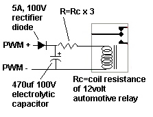


Basically what we're doing here is taking in the pulse width modulated 48volt DC and running it through diode to charge a capacitor.  The diode prevents the capacitor from discharging back to the heaters.  


Ignoring the relay for a moment, as soon as you start to get some pulses from the charge controller, the capacitor will go up to 48volts or so and stay there.  Since the pulse are always 48volts even when they're only on for a few milliseconds (like during very light power dumping) you can assume the capacitor will always be fully charged during almost any amount of dumping.


I would suggest using a 12 volt automotive relays since they're fairly cheap, readily available and rugged.  Obviously we can't send 48 volts into the 12volt electromagnet of the relay so we need to reduce the voltage to 25% of 48volts.  The relay coil will have a certain resistance (probably about 500ohms) so we select a series resistor of 3 times this to drop the 48volts on the capacitor to 12.  In this way 36 volts will be dropped by the resistor and 12 volts by the relay coil.


I'd start with the vaues shown to try things out.  


You don't need to rewire the heat elements yet.  Just go to a local auto-parts store and get a 30amp single pole double throw relay.  See if it gives the coil resistance on the package (some do).  If not you'll need to measure it with an ohm meter.


Next go to Radioshack or some other electronics store and get the capacitor and the diode.  Both of these should have at least a 100 volt rating.  The diode should be rated for at least 5 amps or so.  Get at least a couple capacitors.  For the resistor get a 1/4 or 1/2 watt in whatever value of resistance you calculated.


I'd suggest picking up a bundle of jumper leads with alligator clips on them too.


Connect everything up as shown (paying attention to polarity) and measure the voltage across the capacitor (should be around 48 volts whenever you're dumping) and across the relay coil (should be between 10 and 14 volts).  


Again, you can test the functioning of the relays without modifying any of the existing wiring.  Simply connect the attached relay circuit across the incoming dump power lines.


If you notice the relay "singing" or buzzing then you might need more capacitance.


WIth this circuit, at low values of dumping (a few percent or so) the relays may not click on at all.  In this case all power will be simply be diverted out the external dump load the same as if both thermostats were already hot.


There are certainly more elegant solutions using mosfets, IGBTs etc. but this is pretty straightforward, understandable and easily servicable if there are problems.


Hope this helps

« Last Edit: February 26, 2007, 09:21:43 PM by (unknown) »

(unknown)

  • Guest
Re: Pulsed 360hz DC and AC Contacts?
« Reply #32 on: February 27, 2007, 08:21:40 PM »
Thanks very much. It'll be a bit before I get around to collecting and assembling the parts, but I'll keep you posted when I do.
« Last Edit: February 27, 2007, 08:21:40 PM by (unknown) »