Josh,
Okay here it is:

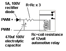
Basically what we're doing here is taking in the pulse width modulated 48volt DC and running it through diode to charge a capacitor. The diode prevents the capacitor from discharging back to the heaters.
Ignoring the relay for a moment, as soon as you start to get some pulses from the charge controller, the capacitor will go up to 48volts or so and stay there. Since the pulse are always 48volts even when they're only on for a few milliseconds (like during very light power dumping) you can assume the capacitor will always be fully charged during almost any amount of dumping.
I would suggest using a 12 volt automotive relays since they're fairly cheap, readily available and rugged. Obviously we can't send 48 volts into the 12volt electromagnet of the relay so we need to reduce the voltage to 25% of 48volts. The relay coil will have a certain resistance (probably about 500ohms) so we select a series resistor of 3 times this to drop the 48volts on the capacitor to 12. In this way 36 volts will be dropped by the resistor and 12 volts by the relay coil.
I'd start with the vaues shown to try things out.
You don't need to rewire the heat elements yet. Just go to a local auto-parts store and get a 30amp single pole double throw relay. See if it gives the coil resistance on the package (some do). If not you'll need to measure it with an ohm meter.
Next go to Radioshack or some other electronics store and get the capacitor and the diode. Both of these should have at least a 100 volt rating. The diode should be rated for at least 5 amps or so. Get at least a couple capacitors. For the resistor get a 1/4 or 1/2 watt in whatever value of resistance you calculated.
I'd suggest picking up a bundle of jumper leads with alligator clips on them too.
Connect everything up as shown (paying attention to polarity) and measure the voltage across the capacitor (should be around 48 volts whenever you're dumping) and across the relay coil (should be between 10 and 14 volts).
Again, you can test the functioning of the relays without modifying any of the existing wiring. Simply connect the attached relay circuit across the incoming dump power lines.
If you notice the relay "singing" or buzzing then you might need more capacitance.
WIth this circuit, at low values of dumping (a few percent or so) the relays may not click on at all. In this case all power will be simply be diverted out the external dump load the same as if both thermostats were already hot.
There are certainly more elegant solutions using mosfets, IGBTs etc. but this is pretty straightforward, understandable and easily servicable if there are problems.
Hope this helps