Author Topic: car alternator rectifier question  (Read 27696 times)

0 Members and 1 Guest are viewing this topic.

mab

  • Sr. Member
  • ****
  • Posts: 429
  • Country: wales
car alternator rectifier question
« on: February 18, 2012, 10:28:50 AM »
Hi, This isn't strictly 'otherpower' but it might save me money  ;) ...

I'm trying to repair my car alternator and having determined that the rectifier has 3 cooked diodes, I was thinking of using a rectifier plate from another alternator; but the original rectifier appears to be 4ph and the new one is only 3ph. The alternator seems to be wired Y 3phase but the star point is connected to the 4th diode pair  ??? .

Can I use the 3ph rectifier and leave the star point unconnected?

And just out of curiosity, why was the star point 'rectified' in the first place?

thx, mab

Watt

  • Guest
Re: car alternator rectifier question
« Reply #1 on: February 18, 2012, 07:41:49 PM »
Is there any chance that alternator with the y connection on the rectifier could be ( for example ) a 21 volt phase to phase with 12 volt nominal phase to y connection?  If so, just make sure you have enough diodes to have a full wave rectifier within that rectifier.  Interesting though, got a picture of it you can post?


Edit: Rereading I realize I am backwards with the donor / transplant alternators.  Same still applies but be careful as rectifying only the phase to phase voltage may lead to too high a voltage if your system uses phase to common voltage as system voltage. 
« Last Edit: February 18, 2012, 07:45:42 PM by Watt »

oztules

  • Hero Member
  • *****
  • Posts: 1477
  • Country: aq
  • Village idiot
Re: car alternator rectifier question
« Reply #2 on: February 19, 2012, 04:41:00 AM »
If you draw it out, it looks like a star delta( or IRP  "switch"..... without the switch.

Meaning ... if the voltage sags too far from heavy loading across the star groups, the voltage  will be independently rectified three single phases until the overload passes.

Thats my best guess.... laugh if you will but thats all it can be I reckon.

So if you ignore it, and leave the starpoint  alone, it will work like a normal one with 6 diodes, minus the overload reserve.

ie the phase differential is about 1.7... delta, but with 3 times the resistance of delta. so when star sags, delta  (irp actually) takes over. Doing this they may use thinner wire or higher gross amp rating.

.........you may begin laughing now.


...............oztules
Flinders Island Australia

dinges

  • Hero Member
  • *****
  • Posts: 1294
  • Country: nl
Re: car alternator rectifier question
« Reply #3 on: February 19, 2012, 10:38:01 AM »
One thing is for sure: your alternator is most decidedly not a 4-phase one, but a 3-phase one, no matter how many diodes are in it.

Had a quick google, as it made little sense to me, but it seems to be done more often (I had never seen this before):


http://autonopedia.org/renewable_energy/Generators/Alternator_Secrets.html

Quote from that website:

Newer alternators particularly high current models, use two additional diodes on the neutral connection to sample alternator output voltage for use by the regulator.

So not sure whether you can get away with using 6 diodes; it probably depends on how the regulator operates....
“Research is what I'm doing when I don't know what I'm doing.” (W. von Braun)

oztules

  • Hero Member
  • *****
  • Posts: 1477
  • Country: aq
  • Village idiot
Re: car alternator rectifier question
« Reply #4 on: February 19, 2012, 02:28:44 PM »
Yes Dinges,

There is a small problem with this.... diodes for regulator control, can be small, I take it that the ones mab is looking at are the 60 amp ones the same as the full wave bridge. Usually the control voltage diodes are little things inside the alt mostly. I struggle to see why they would use beefy ones for the purpose stated in the article.

That aside, the other bloke knows what he is talking about, but I'm not sure these are the same thing. I think same circuit different reason.

If Mab can't find a regulator take off wire from the star point to the reg..... I think the sag theory is the only one that flies. If there is a wire from star point to the outside world.... then I'm wrong.


..............oztules
Flinders Island Australia

mab

  • Sr. Member
  • ****
  • Posts: 429
  • Country: wales
Re: car alternator rectifier question
« Reply #5 on: February 19, 2012, 04:01:14 PM »
Yes it's a full wave (8 big diodes) rectifier - actually exactly like Dingles' circuit - I think - as some diodes are shorted it's difficult to test which point (neutral or phase) is fed to the reg - I'll cut some of the connections to see.

Actually Oztules I think your theory is right - as backed up by Dingles' website - this is a 100A alt - I think that qualifies as high output. I've never seen one like this before either.

It looks like I'd better buy the right rectifier - assuming I can find anyone to sell me just the rectifier - this alt is not designed to allow removal of brushes/reg/rectifier without complete dismantling - evidently you're supposed to just buy a new alt now  >:( 

Thanks folks

mab

Isaiah

  • Full Member
  • ***
  • Posts: 140
Re: car alternator rectifier question
« Reply #6 on: February 19, 2012, 09:02:15 PM »
Yes some of the newer gm alts. 1991 and up  are hard to get apart the wires to  the diodes aer crimped  together and maybe even some solder.
 uep they don't want you messing just spend the $$$and buy a new one. this is progress?

ghurd

  • Super Hero Member Plus
  • *******
  • Posts: 8059
Re: car alternator rectifier question
« Reply #7 on: February 19, 2012, 10:50:47 PM »
It makes sense to me right now, but it is very late at night.
It looks like, sort of, a solidstate automatic Delta-Wye switch to me.

Automotive applications are not restricted to function within the same parameters as wind power.
G-
www.ghurd.info<<<-----Information on my Controller

oztules

  • Hero Member
  • *****
  • Posts: 1477
  • Country: aq
  • Village idiot
Re: car alternator rectifier question
« Reply #8 on: February 20, 2012, 12:14:28 AM »
Do you have a picture?

I find the best thing is to just get at it with the heat gun, (makita or similar electric one), and heat up the heat sinks and remove the diodes... then tackle them one by one.... yes for the feint hearted, the heat gun makes an excellent soldering iron for heavy stuff... alternators in particular.

Then you can just replace the diodes with similar ones from a junked alt.... thats how I fix all the ones on the island... it's free, instant gratification, and uses up old alternators.

Never bought a diode pack for the last twenty or so in the last 7 years here.... did a lot of mix and match though


............oztules
                            ( a simple animal)
« Last Edit: February 20, 2012, 12:47:25 AM by oztules »
Flinders Island Australia

mab

  • Sr. Member
  • ****
  • Posts: 429
  • Country: wales
Re: car alternator rectifier question
« Reply #9 on: February 20, 2012, 05:54:23 AM »
OK, the 1st & 2nd pics show the top plate (-ve) with it's 4 diodes
the 3rd pic is the underside of the rectifier/reg/brusholder assembly showing the other 4 diodes
the last pic shows the winding connections  ((from left to right) phase, phase, star point, wire from starpoint to rectifier, phase).

Do you have a picture?

I find the best thing is to just get at it with the heat gun, (makita or similar electric one), and heat up the heat sinks and remove the diodes... then tackle them one by one.... yes for the feint hearted, the heat gun makes an excellent soldering iron for heavy stuff... alternators in particular.

Then you can just replace the diodes with similar ones from a junked alt.... thats how I fix all the ones on the island... it's free, instant gratification, and uses up old alternators.

Never bought a diode pack for the last twenty or so in the last 7 years here.... did a lot of mix and match though


............oztules
                            ( a simple animal)

The diodes appear to be pressed in - on both alts - how would you get these out?; I never would've thought about trying to replace them individually - I assume that I'd destroy the good diodes extracting them from one plate and would have to somehow press them into the other without damage and ensuring good thermal contact. (I have some quite powerful irons (and a heat gun - though I would never have thought of using that - wouldn't it overheat the diodes?))

Yes some of the newer gm alts. 1991 and up  are hard to get apart the wires to  the diodes aer crimped  together and maybe even some solder.
 uep they don't want you messing just spend the $$$and buy a new one. this is progress?

I could cope with crimped & soldered wires; the thing that gets me is that the rectifier/reg/brushes were INSIDE the main ally shell of the alt - so I had to prize the shells off the windings (which after several years on UK's wet & salty roads was no easy task).

Quote
Automotive applications are not restricted to function within the same parameters as wind power.
G

no indeed - it's all performance - efficiency? what's that??

mab

dinges

  • Hero Member
  • *****
  • Posts: 1294
  • Country: nl
Re: car alternator rectifier question
« Reply #10 on: February 20, 2012, 06:14:11 AM »
The diodes are pressed in, for low electrical and thermal resistance. You could try pressing them out, if that's possible, more disassembly of the rectifier-heatsink may be necessary for that (not sure if the rectifier-block can be disassembled further, and then reliably re-assembled again after you've pressed new diodes in). If pressing them out doesn't work, you may need to resort to drilling (though you could try pulling them out, but strongly doubt that would work - but you might get lucky)

You'd also have to find new diodes and press them in again. If you have to buy the individual diodes (i.e. you don't have a stash of them that can be re-used) I'd try to simply find a complete new rectifier for you particular alternator. These things occasionally fail, and replacements should be available if you look around.

http://www.nationsautoelectric.com/rectifiers.html

Unlike Oztules, you don't live on a remote island where necesssity is the mother of invention, so it may be expedient to simply buy a replacement rectifier. The expense of one isn't outrageous.

It all depends on how you value your time and effort, and whether you have enough suitable replacement diodes - I understand you only have six, whereas you need eight?
« Last Edit: February 20, 2012, 06:18:39 AM by dinges »
“Research is what I'm doing when I don't know what I'm doing.” (W. von Braun)

oztules

  • Hero Member
  • *****
  • Posts: 1477
  • Country: aq
  • Village idiot
Re: car alternator rectifier question
« Reply #11 on: February 20, 2012, 03:32:43 PM »
Pressed ones are my favourite, as they are the easy ones to replace. Simply press them out with a small press or hammer and drift... as close to the same diameter as the diode. They press out best like that. Use a tube the same size as the face to press them in evenly. They are only straight knurled and pressed in.

If it were me and I had another block (which you have I think... so 6 spare diodes there), pop the diodes out of that, and press them into the original one, and your done... it's that simple.

And yes, done this plenty of times before, but unfortunately, most lately have been embedded in solder to get an even better heat path, and be a darn pest.

I think you have all the stuff there to do it in the next hour... nothing to get.

I also build the regulators for the ones that fail over here.... rewind rotors.... etc.


..........oztules

Edit.... those diodes look awfully manly to drive a regulator ..... ;D
« Last Edit: February 20, 2012, 03:39:09 PM by oztules »
Flinders Island Australia

mab

  • Sr. Member
  • ****
  • Posts: 429
  • Country: wales
Re: car alternator rectifier question
« Reply #12 on: February 20, 2012, 06:26:10 PM »
Thanks Oz'; Encouraged by your reply I was about to try drifting out some diodes when I though to check the physical size - my good diodes are 13mm od and the duds in the 100A alt are only 11mm - doh!  >:( Or can I drill out the heatsink? maybe, but truth be told I'm not sure what the current rating of my good diodes are - the rest of the alt having disappeared some years ago.

I've managed to find someone who will supply the rectifier (about £35) so I think I'll probably have to go that way - this time - that's still much better than the £170+ I've see for exchange alternators.

But I think I'll try drifting out the good diodes from this one just to see if it's as easy as you say.   ;)

Quote
Edit.... those diodes look awfully manly to drive a regulator ..... ;D

the reg has a connection to the main B+ terminal and does draw a few mA from there, so I guess it draws it's power direct from there - so no little diodes; It appears to use the signal from the lamp terminal to turn on and energise the rotor coil.

I have built a replacement reg for an alt before - one of the simplest diy circuits I made - basically a 'power' schmitt trigger with a freewheel diode; made it adjustable - my friends were surprised when I ducked under the bonnet for a moment and 'turned up' the headlights one night  ;D ;D .

mab

oztules

  • Hero Member
  • *****
  • Posts: 1477
  • Country: aq
  • Village idiot
Re: car alternator rectifier question
« Reply #13 on: February 20, 2012, 08:50:14 PM »
If it were me, yep drill away... need a fraction undersize for the press fit.

It is easy, only aluminium.

I'm no angel, but I make things work, and where I live, thats worth everything. 

Just make sure the aluminium heat sink is well supported very near the hole your about to press stuff out of or more important, into.


Lets face it, nothing to lose is there?.... so success or bust I say... tally-ho..... sally forth and so on.....

Worst that can happen is a new diode block.... which your looking at doing anyway.


..................oztules

Edit. And to your earlier question.... no solder heat does not worry the diodes in the least.... thats how most alternators hold their's. Only half a dozen alts were pressed in like yours that I have had to work on. I don't think even 450c would bother them. Heat gun is great to do the solder types... they are embedded in the stuff.

My regulator design... fits all and also old generators... just change zener for other voltages 12, 24 etc
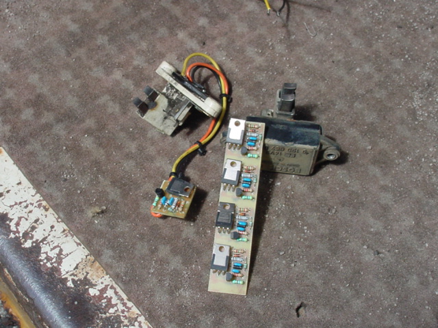
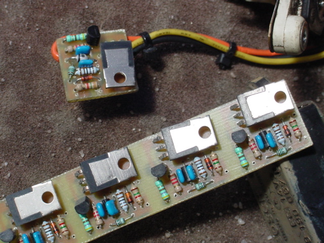
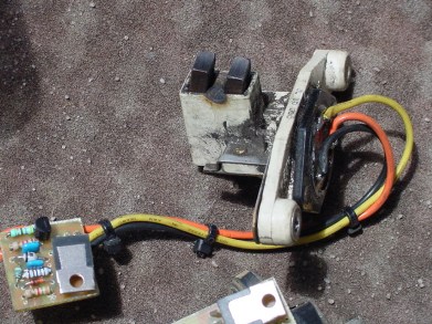

Mostly they fit where the original one was, some not so, unless I try a bit harder.

Costs about a dollar I suppose. I don't charge for them.
« Last Edit: February 20, 2012, 09:39:15 PM by oztules »
Flinders Island Australia

mab

  • Sr. Member
  • ****
  • Posts: 429
  • Country: wales
Re: car alternator rectifier question
« Reply #14 on: February 22, 2012, 09:20:15 AM »
I have to confess I've followed Dingles' advice and ordered a new rectifier assy. Once I've got the car back together I don't want to have to pull it apart again if my substitute diodes (or my installation of them) are not up to the job.

Though I shall certainly use the old one for experimenting in diode replacement as per your advice & keep it as a backup.  :)


thanks

mab

dinges

  • Hero Member
  • *****
  • Posts: 1294
  • Country: nl
Re: car alternator rectifier question
« Reply #15 on: February 22, 2012, 09:52:16 AM »
Quote from: mab
I have to confess I've followed Dingles' advice

Dingles, the half-witted brother of Biggles?

Quote
[...] and ordered a new rectifier assy. Once I've got the car back together I don't want to have to pull it apart again if my substitute diodes (or my installation of them) are not up to the job.

Hopefully Oztules doesn't feel cheated now :-)

But being left stranded out in the field with a broken down car isn't my idea of fun, especially not on the highway; reliability is pretty important - not implying that DIY replaced diodes would have to be any less reliable.... but still. I think that I would've spent the money and bought a replacement rectifier module.

Question: Oztules, do you encapsulate your (very smart looking!) boards in epoxy? Cars are a very harsh environment for electronics, both heat, humidity and, worst of all, vibrations. I think I would encapsulate in epoxy, but since you haven't mentioned it, I assume you don't, and haven't had any problems (recalls...? :D) with it?

BTW, very impressed (once more) with your tinkering. You take it up a level or two from most of us mere mortals.... I hate messing with cars myself but should my alternator require some TLC in the future.... then I know that repairs can be carried pretty far down to the component level.... with the only limit being my willingness to do so, not any technical reasons.

Pity you keep the schematic of your alternator regulators a closely guarded secret.... (wink wink, nudge nudge)... or are they just like the generic schematics one finds on the 'net? e.g. like this:

“Research is what I'm doing when I don't know what I'm doing.” (W. von Braun)

oztules

  • Hero Member
  • *****
  • Posts: 1477
  • Country: aq
  • Village idiot
Re: car alternator rectifier question
« Reply #16 on: February 22, 2012, 04:51:52 PM »
Dinges:
Usually I do encapsulate. They are small enough that most times I mill the original regulator box out, and place this in, and epoxy..

Yes the circuit is a secret to me now.... 2006 i think I did the first one..... and you know I never keep the circuit of anything.... thats not how i develop stuff. It gets designed in PFW and gets etched, tested, changed... re-etched, and keep the last iteration.... here is this ones file.

5045-0

I know I know it does not match the photo... that latest version is on another computer outside in my electronics container (shipping container)... and I'm lazy.. same circuit though, just different real estate allocation to make it a bit smaller still.


.....................oztules

dingles... biggles... i need to get out more:)
« Last Edit: February 22, 2012, 05:27:13 PM by oztules »
Flinders Island Australia

electrondady1

  • SuperHero Member
  • ******
  • Posts: 3120
  • Country: ca
Re: car alternator rectifier question
« Reply #17 on: February 22, 2012, 05:08:50 PM »
map, those are remarkable photographs of your alternator !
(yours are nice too oz)

mab

  • Sr. Member
  • ****
  • Posts: 429
  • Country: wales
Re: car alternator rectifier question
« Reply #18 on: February 22, 2012, 07:16:11 PM »
map, those are remarkable photographs of your alternator !
(yours are nice too oz)

Thanks - having just looked at them again I just realized how much crap I have on my workbench  ;D

Quote
Question: Oztules, do you encapsulate your (very smart looking!) boards in epoxy? Cars are a very harsh environment for electronics, both heat, humidity and, worst of all, vibrations. I think I would encapsulate in epoxy, but since you haven't mentioned it, I assume you don't, and haven't had any problems (recalls...? :D) with it?

Just to add my own 6p worth - When I made a reg for an alt (several years ago) I didn't bother encapsulating it - it was insulation-taped to the plastic ignition module on the side of the engine-bay and despite our regularly wet (and sometimes salted) roads it never gave me any trouble in several years - outlasted the car in the end. I don't have a circuit diagram either, but I based it on a 741 op-amp and a darlington transistor.

Going back to why i've bought a new rectifier - I was thinking that if I still had my old (1971) landrover I'd have tried Oztules repair method; but there are 2 differences:

1. I could remove the alt in 5mins from the landy, whereas this one takes about 1/2 an hour (has a vacuum pump on the back with oil supplied from the engine, and several other bits have to come off first.

2. If the alt went down again on the landy, I could just turn everything off except the ign coil, and could finish work and confidently drive home from anywhere on the battery. This car has electric everything: electric diesel injection, computers, can-bus - even electric power steering  :o  - I don't know what the battery drain is once you lose the alt, but they fitted a 100A alt for a reason - so I would need to get home quick before the battery gave out.

But I still want to try Oz's method on the old rectifier anyway  - I've dismantled the rectifier - just need to sort some drifts and holes...  :)

mab

mab

  • Sr. Member
  • ****
  • Posts: 429
  • Country: wales
Re: car alternator rectifier question
« Reply #19 on: February 23, 2012, 06:45:57 AM »
Well this is interesting; the new rectifier turned up today and guess what? it's got two diodes 'missing' - the two that went to the star point.

Guess that answers my original question.  ;D


oztules

  • Hero Member
  • *****
  • Posts: 1477
  • Country: aq
  • Village idiot
Re: car alternator rectifier question
« Reply #20 on: February 23, 2012, 02:53:11 PM »
Well at least you have spare diodes to press in the holes if you do want the extra current capability.

I think I must have been on the money with my laughable guess.

I cannot see any reliability issues with press and match... diode is a diode is a diode...

But if it gives you just an iota of more comfort with the new ones they are worth it.

Alls well that end well.


.................oztules
Flinders Island Australia

OperaHouse

  • Hero Member
  • *****
  • Posts: 1308
  • Country: us
Re: car alternator rectifier question
« Reply #21 on: February 23, 2012, 05:04:27 PM »
A diode is not a diode..........Least you forget the diode case changes polarity and install the wrong one.

oztules

  • Hero Member
  • *****
  • Posts: 1477
  • Country: aq
  • Village idiot
Re: car alternator rectifier question
« Reply #22 on: February 23, 2012, 06:25:54 PM »
Fair comment Opera.... I had hoped mab was aware why they had the two plates insulated.... but  fair comment.


..............oztules
Flinders Island Australia

mab

  • Sr. Member
  • ****
  • Posts: 429
  • Country: wales
Re: car alternator rectifier question
« Reply #23 on: February 23, 2012, 07:39:39 PM »
Yes I was aware they were opposite types on the two plates thanks  ;) but the supplier of the new rect assures me it'll work fine with just 6 so I've fitted it as is. The car's now back on the road with 14.something volts at the battery.  8)

But I will restore the old one with 8 diodes as a backup.

dinges

  • Hero Member
  • *****
  • Posts: 1294
  • Country: nl
Re: car alternator rectifier question
« Reply #24 on: February 24, 2012, 09:06:00 AM »
Yes the circuit is a secret to me now.... 2006 i think I did the first one..... and you know I never keep the circuit of anything....

Thanks. Took the liberty of tracing it, may save me some effort in the future of having to reinvent the wheel again. Nothing better than a tried & proven design. Maybe others have some use for the schematic as well:

5053-0

So it's no longer a secret to you now then, Oztules :-)

BTW, the older I get, the more meticulously I document my projects for my own future benefit. Got burned a few times too many when working on an old project, having completely forgotten how it worked or even how it was supposed to work. My memory isn't what it used to be.... if I knew how to replace the Lithium backup battery of it, I would have done so long ago....
“Research is what I'm doing when I don't know what I'm doing.” (W. von Braun)

oztules

  • Hero Member
  • *****
  • Posts: 1477
  • Country: aq
  • Village idiot
Re: car alternator rectifier question
« Reply #25 on: February 24, 2012, 02:15:13 PM »
Thanks Dinges......I just get older I think... no wiser


..............oztules
Flinders Island Australia

wcb

  • Newbie
  • *
  • Posts: 4
  • Country: us
Re: car alternator rectifier question
« Reply #26 on: September 27, 2012, 09:37:06 AM »
first post.  Had alternator trouble and found my way here.  wow!  very impressive and inspiring.

i only have a basic understanding of electronics left over from high school, and regulators are new to me.  got some of it figured out but have some questions about this circuit of oztules' i was hoping you could clue me in/correct me if im wrong . . .

I think the three Rs on the far left are a voltage divider for the zener, and the 1k1 R is to bias the bd647 into its active/linear phase, correct?

I take it that the diode across the coil is the "Protection Diode" featured in some other regulator circuits.  Is the function of this diode sacrificial or . . . ?

the 470 ohm R is for what?       my guess is bias for bc337?

the 47n cap?          my guess is filter/smooth signal to bd647?

the 47n cap + 1k8 R?         my guess is negative feedback from bc337?

any help would be awesome.   :)  thanks

mab

  • Sr. Member
  • ****
  • Posts: 429
  • Country: wales
Re: car alternator rectifier question
« Reply #27 on: September 28, 2012, 04:56:17 PM »
I thought I recognized that heading  :)

I suspect Oz or dingles could answer this question better but I'll give it a go...

The purpose of the reg is to turn on the field coil until the output voltage of the alt is greater than the setpoint, then turn the field coil off until the voltage drops below the setpoint; basically it's a voltage sensing switch.

the 1K1 turns on the BD647 so the alternator output increases. When the alt output voltage exceeds the setpoint, the voltage at the base of the bc337 is enough to turn it on; the bc337 turns off the bd647 by shorting its base to 0v. the 1k8 and the cap are a +ve feedback (I think) to ensure that the regulator turns fully off or fully on and doesn't dither about 1/2 on and 1/2 off and getting hot.

Quote
I think the three Rs on the far left are a voltage divider for the zener...
sounds about right - these R's determine the output voltage.

Quote
I take it that the diode across the coil is the "Protection Diode" featured in some other regulator circuits.  Is the function of this diode sacrificial or . . . ?

The field coil of the alt is a big inductor (electromagnet). when the bd647 turns off, the collapsing magnetic field induces a voltage in the coil:- basically this means the current flowing in the coil doesn't want to stop when the BD647 turns off, so the 'freewheel diode' allows the current to flow round and round the coil. If the diode wasn't there the BD647 would get fried when it turned off by the coil 'forcing' the current through it.

Quote
the 470 ohm R is for what?       my guess is bias for bc337?
I think this helps keep the bc337 fully turned off; remember it's working as a switch - fully on or fully off.

hope that helps

mab

wcb

  • Newbie
  • *
  • Posts: 4
  • Country: us
Re: car alternator rectifier question
« Reply #28 on: September 28, 2012, 06:22:39 PM »
cool that helps some.  the brushes on my alternator dont have a diode across them: one terminal the B terminal. 

 i think part of my difficulty figuring this out is how circuits get drawn conventionally, as though the positives are moving to ground when actually its the negative electrons moving from ground through the rest of the circuit.

the caps still confuse me because they dont pass DC current, so they cant be the bias for the bc337.

i was under the impression that regulators were operating in analog, charging the coil proportionally to the match the scale of the loads on the system?  if the coil ever turned off completely, alternator output = 0, and the charge warning light would (hopefully) come on, right?

thanks for the response  :)

mab

  • Sr. Member
  • ****
  • Posts: 429
  • Country: wales
Re: car alternator rectifier question
« Reply #29 on: September 28, 2012, 08:03:56 PM »
the diode in your alternator would have been part of the original regulator - unless it's a very old alt with an electromechanical regulator.

Quote
i was under the impression that regulators were operating in analog, charging the coil proportionally to the match the scale of the loads on the system?  if the coil ever turned off completely, alternator output = 0, and the charge warning light would (hopefully) come on, right?

No; the regs are on or off. The field coil has quite a large inductance so when the reg turns on the current in the field coil (and so the output current of the alt) ramps up (quite slowly - 10's or even 100's of mS); that pushes the battery voltage up. Then, when the reg turns off, the current in the field coil ramps down (flowing through the freewheel diode) and the alt output current ramps down with it.

An alternator output current is a sort of triangle waveform, and they rely on the battery to smooth the voltage (which is why they don't like running without a battery solidly connected).

I think some modern alts might use PWM controllers which give a higher switching frequency but still they are either on or off, just operating in Khz rather than 10's/100's Hz.

you could use an analog controller, I suppose, but it would generate a lot of heat and need a big heatsink, and due to the large inductance limiting the response time you wouldn't get much improvement in voltage control.


bob g

  • Hero Member
  • *****
  • Posts: 1107
  • 8.8kwatt idi diesel thermal conversion unit
    • microcogen.info
Re: car alternator rectifier question
« Reply #30 on: September 28, 2012, 09:04:06 PM »
most all modern alternators, going back 30 years or more are pwm control units, running a several hundred hz.

the controllers such as balmar, xantrex, amplepower, sterling etc are all microprocessor controlled pwm units, that way they can program and control charging to a high degree

bob g
research and development of a S195 changfa based trigenerator, modified
large frame automotive alternators for high output/high efficiency project X alternator for 24, 48 and higher voltages, and related cogen components.
www.microcogen.info and a SOMRAD member

wcb

  • Newbie
  • *
  • Posts: 4
  • Country: us
Re: car alternator rectifier question
« Reply #31 on: October 01, 2012, 09:58:05 AM »
cool.  gaining understanding :)

yeah my alt is connected direct to the + of the battery (albeit at a fusebox junction batteryside of the main 80A fusible link)

its a mid 80s toyota/denso type alt btw.