I've been tweaking the circuit in my
last diary. This is the new one:
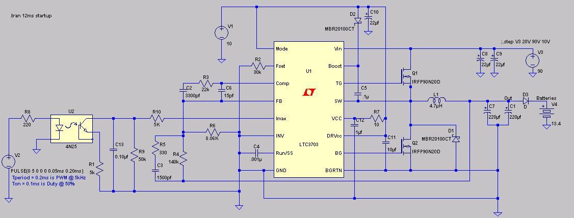
LTSpice Circuit.
I've added C11 and C12 as recommended in the Datasheet. I've also reconfigured the circuit so it looks more like the examples in the Datasheet, and I've added C10 as in the examples.
The nice thing about this chip is that it's a voltage mode controller so it won't have high Amps going through. Imax, the current limiting pin, looks at the voltage drop across the bottom MOSFETs. When this voltage exceeds the voltage at Imax, the chip goes into current limit. The bad thing about this is that controlling the current depends on MOSFET Rdson and circuit configuration (i.e. number of parallel MOSFETs).
The COMP and FB pins are a bit of a pain. The simulation of the circuit in my last post could show nasty 200 AMP spikes at some generator voltages between 20V and 90V. I've modified C2, C3, C6, R3, and R5 (the feedback and compensation circuit) to values in examples in the Datasheet and these AMP spikes are gone. The final circuit will probably need more tweaking for these components.
V2 is now a PWM signal at 5kHz (i.e. 0.2ms period), and I've modified the Imax circuit:
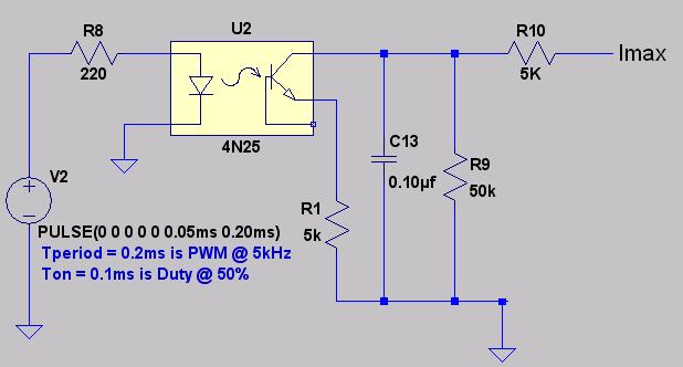
The first circuit had Imax connected directly to the optoisolator. This could leave the Imax pin floating if anything goes wrong with the PWM signal (i.e. micro hangs, etc.), which means there would be no control on current. In this configuration, the resistance at Imax will be 55K (R9 + R10) when PWM duty is 0% (i.e. no PWM signal), which should limit the absolute maximum current to about 70 AMPS. Capacitor C13 smoothes the voltage at Imax and also helps to reduce output current spikes. It also causes the simulation to take longer to reach a steady state. R1 sets the maximum output current at 100% duty and limits the current to about 13 AMPS.
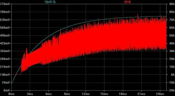
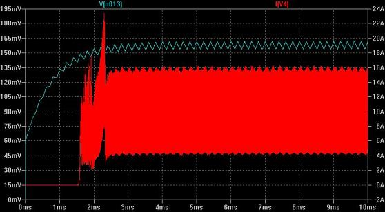
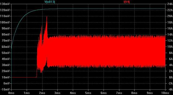
Here are some results from the simulation at different duty cycles. V[n013] is the voltage at the Imax pin and I[V4] is current going into batteries:
At 0% duty:
At 1% duty:
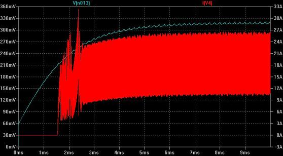
At 50% duty:
At 100% duty:
The response is not very linear (D'oh!). A 1% duty cycle will drop the max AMPS limit dramatically compared to 0%, but a change from 50% to 100% duty doesn't have a big effect. The circuit will need more tweaking, but there's probably a better circuit to control voltage on the IMAX pin with PWM.
Commanda suggested that this may be turned into an MPPT. I'm just trying to keep my flunky windmill from stalling. I guess to get MPPT, the microcontroller would need to know amps going into batteries (small series resistor?), and software to find the maximum power point.
P.S.
All work done under the watchful supervision of a computer expert: