Author Topic: wind powered FET destroyer.  (Read 17914 times)

0 Members and 1 Guest are viewing this topic.

OperaHouse

  • Hero Member
  • *****
  • Posts: 1309
  • Country: us
Re: wind powered FET destroyer.
« Reply #33 on: January 06, 2015, 11:46:10 PM »
That resistor is 15K in his schematic and it is hooked up the way it should be.  Your slipping joestue.

Sorry I don't have the time to get deeply into this, there is a project I have to get out the next couple of weeks.  Bar talk is one thing, to get yourself into someone elses work, understand their nomenclature on schematics enough to see an error takes time and concentration.  I'm pretty certain that this has nothing to do with voltage spikes.  Beginning to doubt even a wiring error.  Waiting around for the wind to blow  and toast a FET is a heck of a way to diagnose a system. When I get time I will mock this up on my water heater and show where the actual problem is.

joestue

  • Hero Member
  • *****
  • Posts: 1763
  • Country: 00
Re: wind powered FET destroyer.
« Reply #34 on: January 07, 2015, 04:58:19 PM »
The RC snubber across the fet (drain to source) is fine, the resistance should be the same as the load, and the capacitance just enough to swamp the leakage inductance of the system.

but an RCD snubber from drain to source only does as much as the resistor can discharge the cap after the fet turns on.. which at 15K won't be anything at all.. and when the fet is off, that 15K is a parasitic load.

15K at 200 volts is 2.4 watts. perhaps it is burnt out already.
« Last Edit: January 07, 2015, 05:02:55 PM by joestue »
My wife says I'm not just a different colored rubik's cube, i am a rubik's knot in a cage.

OperaHouse

  • Hero Member
  • *****
  • Posts: 1309
  • Country: us
Re: wind powered FET destroyer.
« Reply #35 on: January 07, 2015, 07:29:11 PM »
"only does as much as the resistor can discharge"

And here I thought you were an inverter guy.

joestue

  • Hero Member
  • *****
  • Posts: 1763
  • Country: 00
Re: wind powered FET destroyer.
« Reply #36 on: January 07, 2015, 08:15:08 PM »
i know what i said.

at 400 hz a 15 K resistor could work with that topology. it would also dump 2.5 watts continuously at 200 volts on the bus if the dump load is off. This topology is only appropriate for low frequencies. it appears he has a 1/4th watt carbon resistor and that resistor is suspect for self evident reasons. without the resistor, that capacitor will be charged up to whatever the peak voltage is on the drain, which might be 600 or 900 volts, whatever the fet avalanches at.

at 40Khz you could see 600 volts across that 15k resistor when pwming 11 amp loads with sufficient inductance in the system. remove the inductance and you don't even need a snubber.

as the frequency rises the resistance has to decrease, in order to hold the drain down to a reasonable voltage, reducing the resistance increases parasitic loading.

wiring the rcd snubber to the highside removes all parasitic draw, and you can use something sensible like a 10 ohm resistor, which will discharge the capacitor back to zero volts before the fet turns off again.
« Last Edit: January 07, 2015, 08:24:17 PM by joestue »
My wife says I'm not just a different colored rubik's cube, i am a rubik's knot in a cage.

DamonHD

  • Administrator
  • Super Hero Member Plus
  • *****
  • Posts: 4125
  • Country: gb
    • Earth Notes
Re: wind powered FET destroyer.
« Reply #37 on: January 08, 2015, 03:43:53 AM »
Let's keep it civil and calm please.  This is an engineering discussion.

Rgds

Damon
Podcast: https://www.earth.org.uk/SECTION_podcast.html

@DamonHD@mastodon.social

letERblow

  • Newbie
  • *
  • Posts: 40
Re: wind powered FET destroyer.
« Reply #38 on: January 21, 2015, 11:21:58 PM »
I borrowed a storage scope and took some shots of various signals on the FETs.

these scope shots are with the IRFK3DC50 600v 24a which has been operating with the sporatic wind we have had since before christmas. But did have about 16 hours at 1500 watts. The big FET is holding up well and with some low wind times it was a good time to look for voltage spikes or other stray signals.


The RCD snubber with the 15K resistor to - buss does get warm.  I switched FET1's snubber to the high side with 10 ohms. Left FET2 snubber to low side with 500K resistor to possibly see any HV spikes.

current set up
6000 uF capcitors across DC buss
0.22 uF capcitor across DC buss

FET1 has RCD snubber drain to DC + buss, 10 ohm, connected to water heater
FET2 has RCD snubber drain to DC - buss, 500k ohm,  connected to space heater
fast diodes across load resistors
FETs IRFK3DC50   No external gate resistors


FET1, D to S, about 110 v, 2 to 5% PWM on time, 20v/div 50uS/div,gnd at 2nd div
#1
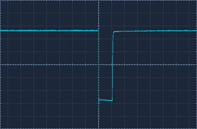
FET2, D to S, about 110 v, 4 to 6% PWM on time, 20v/div 50uS/div, gnd at 2nd div
#2
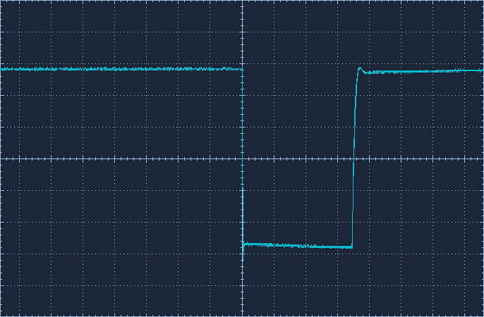
FET1, D to S expanded on signal, about 140 v,  20v/div 200ns/div, gnd at 2nd div
#3
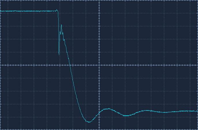
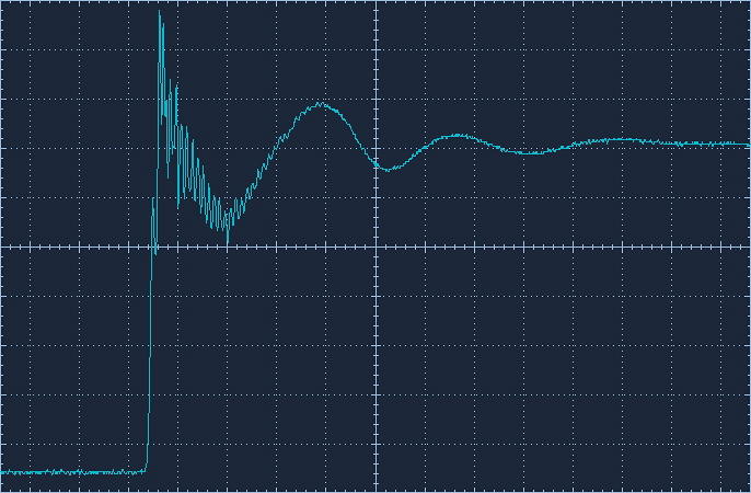
FET1, D to S expanded off signal, about 140 v,  20v/div 200ns/div, gnd at 2nd div
#4

FET1, G to S expanded gate signal, about 140 v,  2v/div 200ns/div, gnd at 1st div
#5
+ Buss to - buss  Ac couple, about 110 v, 2 to 5% PWM, 2v/div 50uS/div,, gnd at center div
#6
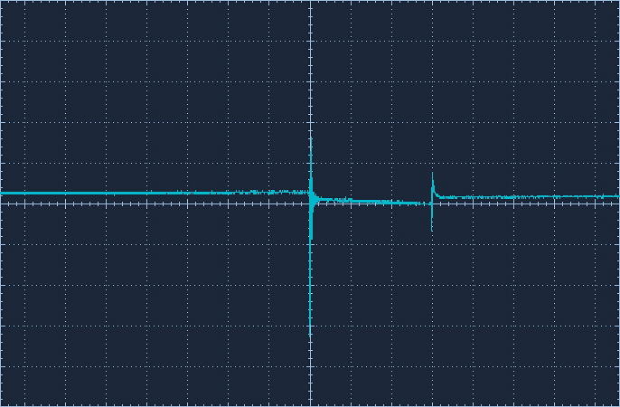
FET1 RCD snubber to + buss, scope cap to -, about 110 v, 2 to 5% PWM on time, 20v/div 50uS/div, gnd at 2nd div
#7
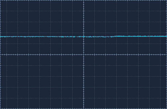
FET2 RCD snubber to - buss, scope cap to -, about 110 v, 2 to 5% PWM on time, 2v/div 50uS/div, gnd at center div
#8
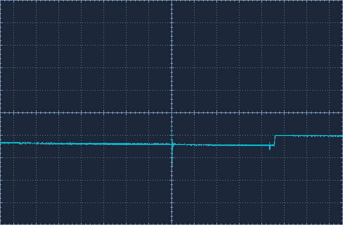
I inserted a 0.05 ohm resistor in line with FET 2 to look at an amp signal but the storage scope does not have a

floating ground so I had to use my battery powered one and can't get a picture of the signal to post. With 150 v on the + buss I saw 650 mv pulses. Calculates to 13 amp pulses. was showing around 3amp on the analog meter.

Not seeing any obvious high voltage spike with this filtering set up I figured it time to try some of the 11N90c fets again. I left the big FET1 wired as it was and replaced FET2 with the 11N90s, same filters. I set FET1 to take

the load and used the HI temperature controls to switch the load to FET2. The software loads both FETs at half PWM for a brief time then switches loads fully so the genny is always loaded.

With about 140v on the + buss, 8 to 10 % PWM, single FETs, 470 ohm gate resistors
The first 2 FETs I tried shorted instantly.

FET#3 I switched on and off 6 to eight times for maybe 3 seconds, then left it on for about 2 minutes before it got real hot and fried / shorted.

FET#4 changed to 100 ohm gate resistor, switched on and off a few times recording D to S signal then left it on for about a minute while monitoring temperature. went from 25c to 60c in about a minute then shorted and cooled off. I

lost this saved scope signal but it did not have any spikes, just the little dip at the bottom on the turn on like the big FETs.

some  conclusions -
1- the problem is the pulsed drain current is too high for the lower rated FETS, my higher buss voltage may also be a contributor.
2- paralleled FETs don't turn on at the same time 
3- One high current FET to replace parallel ones
   the IRFK3DC50 is seem kinda expensive, $20 but has 2 in a package so $10 per FET, one has to    be a spare.
   4 US supplied 11N90s at $16.
   Circuit board less complicated
4- chinese FETs are crap. who woulda thought

The day after these tests the genny had been putting out around 2KW for 6 hours, and low wind during most of the past couple of weeks, the big FETs are hanging in there.


A day or two after the above testing I got curious and wanted to see if I could see if the snubber diode and  filters were really doing any good.

Took the snubber diode off of the space heater load and took some expanded shots of the ON and Off signals of the drain. They looked exactly the same as with the snubber diode on.

Got to feeling brave and took the RCD snubber and RC network off, BAD mistake, the big FET2 shorted instantly. Didn't even get a chance to catch a scope shot.

That bummed me out, killing my $20 FET. Switched over to the spare FET, put snubbers back on. The FET was running ok at around 800 watt load. I guess this is proof the snubbers are protecting the FETs, possibly can't see voltage spikes because the snubbers are dong their job damping them out.

Both RCD snubbers tied to + buss with 10 ohm resistor.

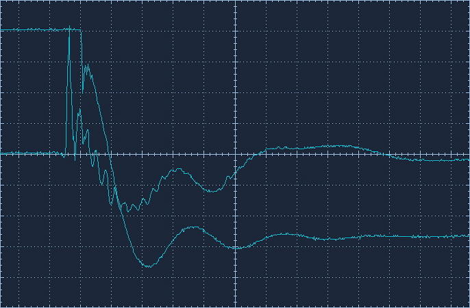
Here is a scope shot of the expanded ON signal of the FET D to S with a shot of the cap to - of the RCD snubber ( center signal, 5v/div, 200 ns, AC couple) The snubber + pulse lines up with the - pulse of the drain signal( got offset in capturing, dumb scope only captures one trace at a time on a dual trace scope) Not sure if it tells us anything useful.
#9
I'm a bit poorer, not much smarter, still have questions, behind on other projects, but have a control system that is working for now. Will just have to monitor it and see how it performs.

Thanks to all for looking and the suggestions, they are keeping my FETs alive!

OperaHouse

  • Hero Member
  • *****
  • Posts: 1309
  • Country: us
Re: wind powered FET destroyer.
« Reply #39 on: January 23, 2015, 05:15:54 PM »
Been busy.  Your FET driver input looks disasterous, not that I actually can see it  The driver chip basically has a floating input with nothing pulling it low.  No wonder it wants to oscillate.  The LED acts like a zener never allowing it to go to common.  Put the LED in series with the input and let the resistor tie the input to ground.  Fix that and you are likely good to go regardless of FET.

I did an opto isolator test using the PWM number set to 1.  Notice the time delay and how it shortens the pulse depending on trip point.  This is why it is advisable not to let PWM drop below 4.

OperaHouse

  • Hero Member
  • *****
  • Posts: 1309
  • Country: us
Re: wind powered FET destroyer.
« Reply #40 on: September 21, 2015, 01:26:10 PM »
Dis you ever fix that floating driver input?  Note the input has a resistor and LED to ground.  That LED acts as a zener and lets the input float and allows it to oscillate with any noise pickup.  You need a resistor from the input to common, as a minimum 1K.  I sent you a couple PM but we haven't heard from you since.

letERblow

  • Newbie
  • *
  • Posts: 40
Re: wind powered FET destroyer.
« Reply #41 on: September 22, 2015, 02:48:21 PM »
I did fix the floating driver input problem and with the larger FETs had a very good 6 month run, not a single control problem. Got distracted and forgot to post the good results. Then a high voltage issue popped my stator and then had some health problems so I am just in the process of dropping the genny to find out if it is repairable.  Thanks for thinking of me.