(hope this didn't post more than once... had problems getting it to post)
OK, so I looked and looked for info on the web about this, and it seems I'm treading where no man has gone before… at least, not down this specific path.
My need is for an alternator, phase count is not important (though I do understand the benefits of 3-phase smoothing), but “smallness†is critical. So, I an endeavoring to convert a large/flat “outrunner†style BLDC into a low-speed alternator.
I am trying to find someone who can help me with a rewind… pro's and con's, best output Power at the lowest speed – up to about 300RPM if possible (which is why I posted it here, in the "Wind" board. I figure it may be useful to others here.
What I bought (ouch) to work with is a pair of HobbyKing Turnigy LD9017 Gimbal motors… made specifically for very low rotating speeds, low power, sine-wave drive, high positioning torque.
http://www.hobbyking.com/hobbyking/store/__53946__Turnigy_LD9017_Brushless_Gimbal_Motor.htmlThey also sell a version wound with heavy multi-strand wire, made for direct-drive of huge (26â€) multi-copter rotor blades… it's rated for 2600 Watts (yes, 3.5HP), 105RPM/V, max. 117A (and this isn't even their biggest one, which is capable of 2800 Watts)
http://www.hobbyking.com/hobbyking/store/__56935__Turnigy_9014_105kv_Brushless_Multi_Rotor_Motor_BLDC_.html(want bigger?
https://www.youtube.com/watch?v=fHDh3IFQ8hY&x-yt-cl=84359240&x-yt-ts=1421782837The LD9017 spec's: (mostly mfr published, corrected according to ‘real' parts received)
Radial Flux
Poles: 24 Stator poles/teeth; 28 magnet Rotor
KV (RPM/V): 9 (per mfr spec)
Resistance: 18 Ohm's (per 2 windings in series in "Wye" connection)
Wire: 0.27mm with 110 turns
No Load Current: 0.1A @ 14.8V
Motor Dimensions: 90x30mm
Weight: 415g
My additional measurements…
STATOR:
18 layers of 0.5mm steel
(total stator thickness: 9mm + a little epoxy)
Tooth depth: 14.7mm
Total Stator depth (tooth depth plus inner ring thickness): 17mm (seems to be the "17" part of the p/n)
Stator Pole Face: 7.77mm wide (by 9mm thick)
Stator tooth winding width: 4.44mm (by 9mm thick)
Stator Pole Face gap: 2.55mm (between pole faces)
Stator OD: 80.1mm
ROTOR:
Rotor magnet ring ID = 81.17mm
Individual magnets are 10mm tall (slightly taller than 9mm stator poles)
Magnet strength: unknown
Stator/Rotor gap: 0.535mm (81.17-80.1=1.07mm/2)
I made a simple test: (wired in Wye/star fashion)
RPM = 350 (the speed of my cordless drill on low speed)
VAC RMS = 27.4/phase
Raw kV = 12.8
Using a Schottly diode (low Vf) 3-phase bridge rectifier and a 1,500uF cap, my best power so far (stock config.) was:
341 RPM, 15.90V DC @ 1.06A = 16.85 Watts
(349 RPM, no load = 39V DC)
Yuk.
Re-wired as Delta (all else the same): 343RPM, 11.0V DC @ 1.47A = 16.13 Watts.
Will it even do more? Yes… in Delta, at 1060RPM I get 42V DC at 2.73A = 112 Watts… Nice… but would require much more mechanical drive complication to reach 1,000+ RPM.
Since it's 24-tooth and 28 magnets, I can split the entire motor in-half electrically, and treat it like 2 12/24 machines… so I did. Split the windings in half, paralleled them, and got… the same maximum power (makes sense now, same copper, same wind config, same power… duh)
At best now in “Wye†(Star) I get:
367RPM, 21V DC @ no load / 339 RPM, 3.62A DC, shorted
347RPM: 9.04V DC @ 1.81A = 16.34 Watts
Delta wired:
332RPM: 5.83V DC @ 2.16A = 12.59W (the diode drop is a larger percentage now at these low voltages)
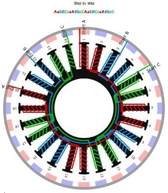
It's currently wound as: Aa bB Cc aA Bb cC (repeat)
I'm not afraid to rewind… but I admit I do not know, nor can I find, what the best winding configuration is for low RPM. I don't care about cogging… I will have plenty of initial torque to drive it (it's not wind turbine… but could be useful for others)
Any generator/alternator “pro's†here?
I considered: AaA bBb aAa BbB – but that can only give me 2-phase with the tooth/magnet ratio, and only about 6-7° out-of-phase.
I've attached an image I found while trolling around… it's essentially this: