If you haven't already done so, I suggest you read the previous installments here;
Part 1
http://fieldlines.com/board/index.php/topic,131213.0.htmlPart 2
http://www.fieldlines.com/board/index.php/topic,131214.htmlPart 3
http://www.fieldlines.com/board/index.php/topic,131215.htmlPart 4
http://fieldlines.com/board/index.php/topic,131296.0.htmlAs mentioned at the end of part 4, this is how to extend the circuit to make a nite-light.
Whilst mains powered nite-lights are prolific in almost any $2 shop, I have yet to see one
specifically for running off 12 or 24 volts.<p>
My original intention with this was to use a phototransistor. And whilst circuit 5.0 does indeed work,
it is less than what I would describe as optimal. It suffers from a lack of sensitivity, and tends to come on too early.
Also, the phototransistors tend to be very directional.
At night, if you turn on the overhead room light, the nite-light won't switch off unless the phototransistor is
aimed directly at the light. But then it tends not to see the daylight coming in through the window.
It also has a fairly wide transition range, where it's not fully on.
So, having explained the short-comings of this circuit, I present it here anyway; with a photo of the bread-boarded prototype.
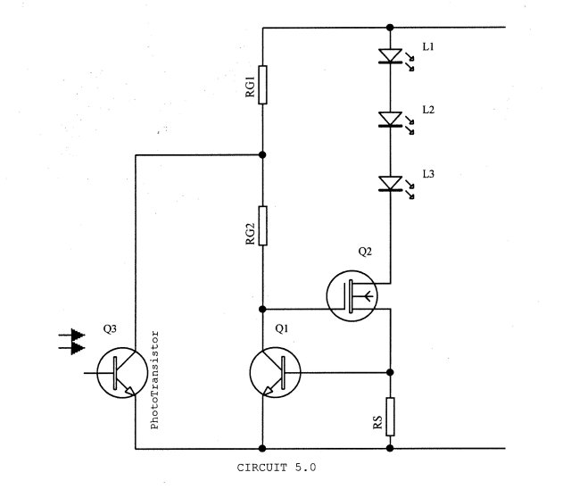
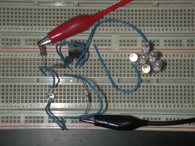
Note that is important to shield the phototransistor from the leds. It is usually necessary to point the phototransistor
90 degrees away from the leds, and then cover the underside of the phototransistor with opaque tape.<p>
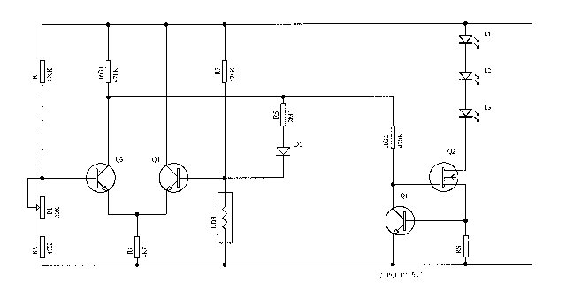
Circuit 5.1 is a bit more complex, but gives very satisfactory performance. Q3 & Q4 form a differential pair. Basically, if
Q3 is on, Q4 will be off. And vice-versa. When there is no light, the LDR resistance will be high. So the voltage at the base of Q4
will be higher than the voltage at the base of Q3. So Q4 will turn on, and Q3 will turn off. Q3 off will allow gate voltage on the fet,
and the leds will turn on.<p>
When light is applied to the LDR, its resistance will be low, so the base voltage on Q4 will be lower than the base voltage on Q3.
Q3 now turns on, preventing gate voltage from being applied to the fet, so the Leds will not be on.<p>
P1 is optional, and can be used to fine tune the sensitivity of the circuit.
R5 & D1 is also optional. It provides positive feedback to enhance the switching from off to on, as well as hysteresis.<p>
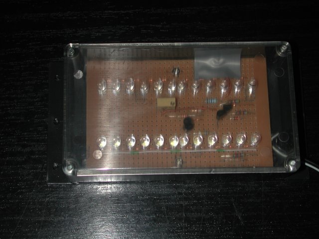
My first unit built on the circuit of 5.1 has been running off a 24 volt plug-pak in my bathroom for some time now.<p>
The component values shown are for my 24 volt system. You may need to decrease the values of R1, RG1, RG2, and R3 for a 12 volt system. (based on feedback from richhagen with experience of the previously published circuit 4),
Again, the LDR should be pointed 90 degrees away from the leds, and the underside covered with opaque tape.<p>
I've also just cornered the Australian market for LDRs. I ordered 10 pieces, and received 10 packets of 100 each. (1000 pieces).
Amanda
