Author Topic: new axial design multirotor  (Read 5101 times)

0 Members and 1 Guest are viewing this topic.

Adriaan Kragten

  • Hero Member
  • *****
  • Posts: 1158
  • Country: nl
Re: new axial design multirotor
« Reply #66 on: January 27, 2023, 06:35:57 AM »

That is almost enough to charge a 12-volt battery. To charge the 12-volt battery, you need at least 14.8 DC volts.

Ed

This is very high and a full battery will be damaged if it is charged with such a high voltage. The maximum charging voltage for a 12 V lead acid battery is normally taken 13.8 V if the battery is almost full to prevent gassing. Even for a smaller voltage than 13.8 V, an almost empty battery can be charged with a large current.

leviatan

  • Newbie
  • *
  • Posts: 46
  • Country: uy
Re: new axial design multirotor
« Reply #67 on: January 27, 2023, 08:47:02 AM »
Thanks for the clearly detailed formulas. But it was not clear if it is correct to measure the current with only two poles instead of the 16 that the rotor would have. Because I imagine that if in the same period of time of 1 second, if instead of passing the north and south poles only once, they pass 8 times something should raise the current there (it is my assumption) and maybe if I do the calculation with Only those two poles, as soon as I assemble the rotor with its 16 poles, there may be a large difference in voltage and current.
I had also measured the direct alternating current without the rectifier and it reached a maximum of 1.20 v.

The thickness of the wire would be 1.2 (in the final coil) so the number of turns would fall to one third, and that would also make the voltage drop, but I try to find a practical reference to know if it is a lot or a little voltage, for only two poles over the coil at 84 rpm.

I usually see in the videos that people assemble the rotor and then test it, I don't have the correct size magnets yet. And even with the 20 pieces that I had, they were not enough to simulate the size of the magnets that I have budgeted (you can see in the photo on one side I have stacks of 3 magnets and the next ones are only 2).
But I am sure that the current and the intensity should vary if in the same period of time the two poles pass 8 times than if they pass only once. The issue is how much they should vary, and I don't know if there are formulas for that.


Bruce S

  • Administrator
  • Super Hero Member Plus
  • *****
  • Posts: 5374
  • Country: us
  • USA
Re: new axial design multirotor
« Reply #68 on: January 27, 2023, 09:13:08 AM »
leviatan
You are doing just fine. What you are measuring right now is only the open voltage, current will not come into play until you have a load attached and changed your meter to read Amperage (Current).

Bruce S
A kind word often goes unsaid BUT never goes unheard

leviatan

  • Newbie
  • *
  • Posts: 46
  • Country: uy
Re: new axial design multirotor
« Reply #69 on: January 27, 2023, 09:27:01 AM »
yes i know that, but dint exist a posibility to produce a measureable and accurate current with only one coil and two poles, then i can only test the open voltage by the moment. I hope this days the chinese back to his tasks, and something advance, at least to got the  4 magnets samples by courrier to do a test with the right magnets. because right now, i dont know if that magnets of differents grades and sizes (than my chosed size and grade) they will be representative of what the correct magnets will generate.

MagnetJuice

  • Hero Member
  • *****
  • Posts: 558
  • Country: ca
Re: new axial design multirotor
« Reply #70 on: January 27, 2023, 11:01:32 AM »
This is very high and a full battery will be damaged if it is charged with such a high voltage.

We are not talking about car batteries or batteries used for standby power. We are talking about deep cycle batteries used for wind power.

Besides, anybody that has a windmill and uses batteries to store the power, knows that after the battery is fully charged, the voltage must be dropped to the floating voltage. You are referring to that voltage. The charge controller takes care of that.

We are talking about charging voltage from a windmill. Do you know anybody whose 12-volt windmill produces a maximum 13.8 volts? I don’t.

Deep cycle batteries should be charged at 14.7 volts. To say that 14.8 volts is very high is an exaggeration.

Ed
« Last Edit: January 27, 2023, 11:36:13 AM by MagnetJuice »
What can I do TODAY that would make TOMORROW a better world?

Mary B

  • Administrator
  • SuperHero Member
  • *****
  • Posts: 3177
Re: new axial design multirotor
« Reply #71 on: January 27, 2023, 12:38:53 PM »
eddy current is going to be bad news in that aluminum...

MagnetJuice

  • Hero Member
  • *****
  • Posts: 558
  • Country: ca
Re: new axial design multirotor
« Reply #72 on: January 27, 2023, 12:43:41 PM »
As Bruce said, now you are measuring open volts only.

I assume that you want to know CURRENT, and what will be your total alternator output in WATTS.

That will depend on the number of magnets (poles), the size (face area) of the magnets, their depth (thickness), the strength (grade) of the magnets and how fast they are passing over the coils (RPM).

Only you have that information.

If I had that information, I could give you an approximate value for the final output in watts.

But I cannot do it using the magnet configuration shown in the picture of your testing setup. I don’t think anybody else can do it either.

Moreover, I think that you should hold up ordering more magnets until you do more testing.

Ed
What can I do TODAY that would make TOMORROW a better world?

leviatan

  • Newbie
  • *
  • Posts: 46
  • Country: uy
Re: new axial design multirotor
« Reply #73 on: January 27, 2023, 02:32:48 PM »
I need to try at least 4 pieces of 100x40x10mm magnets and see the differences with these that I have from experimentation (this blocks are n52 theoretically).

My concern is that the company that gave me the best quote for the magnets, said in principle that they would not make samples, that the 160 pieces ordered in principle would be the "samples."
Since I don't know if going down to grade n35 and increasing the mass of the magnets can do exactly the same as making smaller magnets but at grade n52 (prices skyrocket at that grade, while the strength of the field goes up slightly) I need to try first 4 magnets of that grade and see if they generate a strong enough field at 16-20mm distance between them.

For this reason, I explained to the seller that under no circumstances would I accept that they cut the entire production of the 160 pieces without first testing the field of what they designate as grade n35 (they could even be worse than that grade) and then under pressure from that I was not going to buy them, he asked me to wait until the end of the license for the new year to be able to produce the samples.

Today the license in China ends, I hope on Monday to hear if they are going to cut only 4 pieces. If it were a company that I already knew, I could trust that what they were going to deliver corresponds to or specified, but it is the first time that I have contacted this company, and once the merchandise is delivered there is no going back, no matter what. if it's rubbish.

But I am not going to buy all the magnets before I have tested the quality and results, of course.

My doubt is if there was any formula to know the increase in voltage (actually the watts are not what worries me the most at this moment) based on what only 2 poles produce. If only the voltage would stabilize at its maximum peak (using the 18 poles of the rotor), or it would induce a little more than the voltage that I already have.

That would allow me to have an idea of ​​how many coils I need and what type of connection would be necessary (parallel or serial) for the output of their rectifiers.

But i need a reference point at least, and for that i need 4 magnets of the right size.
Let see the next days what i can solve with the chinese factory.


MagnetJuice

  • Hero Member
  • *****
  • Posts: 558
  • Country: ca
Re: new axial design multirotor
« Reply #74 on: January 27, 2023, 02:48:11 PM »
Can you order magnets from the U.S.A.?

What can I do TODAY that would make TOMORROW a better world?

leviatan

  • Newbie
  • *
  • Posts: 46
  • Country: uy
Re: new axial design multirotor
« Reply #75 on: January 27, 2023, 05:13:36 PM »
i ordered the  tiny block samples from a usa store, but for the rest of parts i need to bring from china with the rest of my import. Elsemore the prices have huges differences like a 50-60% more cheap in China. And i can produce a custom shape there.  That differences force me to shop in china, USA stores are discarded for the huge difference in price and in the most of the cases are retailers, theys cant produce the magnets, only sell the most commoun sizes and shapes.

MagnetJuice

  • Hero Member
  • *****
  • Posts: 558
  • Country: ca
Re: new axial design multirotor
« Reply #76 on: January 27, 2023, 06:10:44 PM »
These two places have a good selection of magnets, and the Grade is as advertised.

I know because I have purchased hundreds if not thousands of magnets from them.

https://www.magnet4sale.com/ and

https://appliedmagnets.com/ - which is same company as https://www.magnet4less.com/


Personally, I would not take a chance with an unknown Asian company that communicating and connecting with is difficult.

If you are interested, I can give you the dimensions and specifications of one of my alternator designs that I think will work well with your Savonius. That way you will have more options.

Ed
What can I do TODAY that would make TOMORROW a better world?

leviatan

  • Newbie
  • *
  • Posts: 46
  • Country: uy
Re: new axial design multirotor
« Reply #77 on: January 27, 2023, 09:07:44 PM »
yes i can see your design to take ideas, i saw any kind of axial PMG on you tube  but the results are not as amazing as the patience and skill of the builders.

I just finished doing some other tests with the coil. I am a fan of the pragmatic, I only take the formulas as a reference, if I do not see a physical proof of the effects I do not trust too much the predictions in very complex things .
 I opened the gap of the magnets to 21mm instead of the original 16mm (the coil is still 10mm thick but with fast revs it is very difficult to keep the coil straight all the time without some other tool holding it to the lathe holder).
Then i run the lathe at 84 at 140 and at 230 rpms.

My conclusions are that at least those small stacked magnets (which shouldn't be the best option) maintain enough magnetic flux at a saturation level because I notice almost no difference in the maximum peak voltage.
From the 1.3v peaks I've seen today tomorrow, I'm now peaking at 1.2v ac at 84rpm. Early today I had achieved 1.3v maximum at the same rpms and 16 mm of space between the magnets.

I was convinced by instinct and some statements by Adrian that the cutting speed of the coils was extremely decisive for the voltage (the larger the rotor diameter, the more tangential speed and more coils)
Maybe it will generate more amperage, but in terms of voltage when I go from 84 rpm to 140 rpm (near of the double of speed) the jump in peak voltage was only 1.2-1.3 to 1.6-1.7v. I would have imagined that with almost twice the speed it would easily reach 2v.

And when I take it to 230 rpms (a limit that I think my rotor will never reach in even severe storm conditions) the voltage jumps to 1.9-2v only. The only perceptible difference is that it maintained the voltage peak continuously (as if it were a rotor with all poles).

I can then imagine that the voltage per coil does not vary linearly with the increase in cutting speed of the coils. It is probable that if the amperage increases a little more (which I don't think I can measure with so little generation).

Probably having the rotor all poles if there is a small rise (or maybe not so small) of the voltage if the voltage peak per coil is maintained longer due to a greater number of pulses in the same time and the coils of one phase add their voltage (like you said in your calculates today)

The gap between the magnets does not determine the peak voltage as much, as long as it is saturated.
So I hope my magnets manage to saturate those 20-21mm with magnetic flux like these small stacked bars do.

But what you did notice towards dramatic changes in voltage jumps was the amount of copper exposed to the magnets.
If you exposed only half of the coil, the voltage would also drop by half.
So the amount of copper that cuts the magnetic flux is very important, or the part of the copper that was not exposed to the field gave me a lot of resistance and consumed part of the electricity that the other half generated.

But at first glance, I need a lot of big coils to maintain reasonable tension at low rpm. The 72 coils 5 or 7mm high should be able to do it. But if I choose to make them 7mm high it would be almost 23 kilograms of copper and if they were 5mm high it would be about 17 kilograms.

Quantity that does not scare me for its price (because compared to magnets it is 5-6 times cheaper) but it is a lot of kilos that are added to the generator set.
Now, taking into account that commercial 70-100 rpm generators weigh around 70-80 kilograms, I imagine that I can do something that reaches 60 kg but with a lower generation speed, I hope at least.

How much copper you spent in your PMG to got your target?? sentme PM with the details if you like or by email if you prefer.


MagnetJuice

  • Hero Member
  • *****
  • Posts: 558
  • Country: ca
Re: new axial design multirotor
« Reply #78 on: January 27, 2023, 11:39:08 PM »
OK, I will finalize my calculations and do some drawings tomorrow. I like drawings instead of just words because it makes it a lot easier to visualize and understand.

As far as PM or email, I rather post it here in the forum, because if the information is useful, not only it will help you, it could help a few hundred of other users.

I have a big project to do tomorrow, so I will be away from the computer most of the day. I should be here late in the day.

The following is something that I had posted on another thread last month to help a guy from Guatemala.

I copied and pasted it from the other thread. I hope that the information is helpful to you.

Voltage from the coil depends on many things.

1 - Number of turns. If a coil has 50 turns and produces 1 volt, doubling the turns to 100 will produce 2 volts. That is only if the magnet is thick enough. Thin magnets will not double the voltage in the coil.

2 - The thickness of the coil wire affects only how much current (amps) can safely flow through it. Wire thickness doesn’t affect the voltage, only the number of turns does.

3 - The speed that the magnet passes over the coil affects the voltage. If the speed (RPM) is 100 and produces 1 volt, 200 RPM will produce 2 volts.

4 - Magnet strength. N-45 Neodymium is stronger than N-42. N-52 is very strong and produces the most voltage.

5 - Magnet area. If a magnet is 2 x 1, it will produce two times the voltage than a 1 x 1 magnet can produce.

6 - Magnet thickness. The thicker the magnet, up to a point, the more voltage it will induce in a coil. The flux from a thin magnet cannot reach all the way through the coil; therefore, it will not induce a lot a voltage. If the magnet is thin, adding more turns to the coil will have little effect on the voltage produced.

7 - Distance from magnet to coil. The closer the magnet passes over the coil, the higher the voltage will be.

What can I do TODAY that would make TOMORROW a better world?

MagnetJuice

  • Hero Member
  • *****
  • Posts: 558
  • Country: ca
Re: new axial design multirotor
« Reply #79 on: January 27, 2023, 11:45:06 PM »
leviatan,

I just saw your PM. I took note of it.

Thanks  :)
What can I do TODAY that would make TOMORROW a better world?

Adriaan Kragten

  • Hero Member
  • *****
  • Posts: 1158
  • Country: nl
Re: new axial design multirotor
« Reply #80 on: January 28, 2023, 03:53:15 AM »
This is very high and a full battery will be damaged if it is charged with such a high voltage.


Deep cycle batteries should be charged at 14.7 volts. To say that 14.8 volts is very high is an exaggeration.

Ed

I said that 14.8 V is very high if the battery is almost full. If the battery is not full, you can use a higher maximum charging voltage than 13.8 V but this doesn't mean that the battery isn't charged if the voltage is lower than 14.8 V. The battery is charged as soon as the charging voltage is higher than the open voltage and the current increases about with the difference in between the charging voltage and the open voltage. Many people use a maximum charging voltage of 13.8 V for a 12 V lead accid battery because then a simple voltage controller can be used which limits the maximum charging voltage to that level. If you allow a higher charging voltage if the battery isn't full, you must measure the charging state of the battery and regulate the maximum charging voltage depending on the charging state. Measuring the charging state is rather difficult as you have to measure the acid rate of the sulfuric acid.

If there is a load connected to the battery during charging, like we have if the battery is connected to a wind turbine, it is not enough to measure the current, the voltage and the charging time to know how much energy has gone into the battery because the battery has a certain efficiency and therefore more energy must be put inwards than that what has gone outwards because of the load. The battery efficiency depends on the current and after a certain time, the charging state becomes uncertain even if current, voltage and charging time are measured. The capacity of the battery also decreases if the battery becomes older.
« Last Edit: January 28, 2023, 04:33:13 AM by Adriaan Kragten »

MagnetJuice

  • Hero Member
  • *****
  • Posts: 558
  • Country: ca
Re: new axial design multirotor
« Reply #81 on: January 28, 2023, 11:35:19 AM »
On January 27, MagnetJuice said:
To CHARGE the 12-volt battery, you need at least 14.8 DC volts.

I assumed that the battery needed to be charged.

On January 27, Adriaan said:
This is very high and a FULL BATTERY will be damaged if it is charged with such a high voltage.

On January 28, Adriaan said:
I said that 14.8 V is very high if the battery is ALMOST FULL

No, you said FULL BATTERY

On January 28, Adriaan said:
If the battery is not full, you can use a higher maximum charging voltage than 13.8 V

Yes. For example 14.8 volts. Just like my original statement.

I am glad that you agree with me.
What can I do TODAY that would make TOMORROW a better world?

leviatan

  • Newbie
  • *
  • Posts: 46
  • Country: uy
Re: new axial design multirotor
« Reply #82 on: January 28, 2023, 04:56:23 PM »
regarding statement no. 3. I have a discrepancy, the linear increase can be given (or even more according to the type of connection that exists between all the coils) but not directly in a single coil.
If you use the product of all the connected coils in a complete stator, a small change in the voltage of a single coil can double or triple the final voltage of the entire rotor.
But when it comes to the voltage generated in a single coil the voltage increase is not linear with the speed of rotation. I can also glimpse that when there are 18 poles going through the coil instead of 2 as in the test I did, that little jump that occurs with a pair of poles could also be magnified by the added effect of the other poles. Just as the current product of all the coils is added, the product of all the induction pulses of the magnets must be added.

In practice with a complete stator and a rotor with all its poles, the effect should be given that a change of doubling the speed doubles the voltage.
Which is something you notice in the commercial 48v generator, but much more, because all the coils are connected in series.
 In the same model but at 12v, the increase in voltage by doubling the speed is barely 60-70%. In the 48v doubling the speed tripled the voltage.

////////////https://youtu.be/uyqfsrVwZF8
like you can see in the video in 84 rpm i got AC 1.2 like maximum, at 140 rpm ( near of the double) i got only 1.5v ac like maximum, and in the last test at 230 rpm ( almost the triple than the first test) the voltage rise to only 2.1 like maximum. The diference, this time the voltage was more continuous. But increase in voltage was less of the double than the generated at 84 rpm and should be at least 3.6v if we take the statement no. 3 like a fixed rule. The final voltage of the complete stator will depend much more on the type of connections between the coils than on the increase in speed of rotation.

It is in this part that I should play a lot with the output of each rectifier to see if I am connecting them in series or in parallel. But for the size of the generator, which I am envisioning, 12v is going to fall short, I probably have to bet at least on 24v, if not on 48v.


JW

  • Development Manager
  • Super Hero Member Plus
  • *****
  • Posts: 4049
  • Country: us
    • Flashsteam.com
Re: new axial design multirotor
« Reply #83 on: January 28, 2023, 06:01:55 PM »
I am a recertified ASE Master tech since 1993. Within the past ten years or so I made ASE Advanced Level Specialist with a high certification score. Also I worked as a Process Engineer for over 15 years, have 3 US Utility Patents. Study Thermodynamics since the eighth grade in high school. Which I also read most of Forest Mimms books going back then, solid-state electronics logic functions.

My point is this. "maybe your measurement of voltage is being skewed somehow"

For me it happened when my temperature measurement did not jive with the Steam Table oh it was a disaster of epic proportion's with my steam engine piers at the time.

Turns out I was using a direct metal contact thermometer. That was the problem. Years later I was measuring the aperture with a non-contact thermometer. After that everything when into perfect context and this then jived with the Steam Table. I was getting outstanding pressure the whole time thru the whole operating range. That's why it was so confusing.

JW   
« Last Edit: January 28, 2023, 06:24:22 PM by JW »

JW

  • Development Manager
  • Super Hero Member Plus
  • *****
  • Posts: 4049
  • Country: us
    • Flashsteam.com
Re: new axial design multirotor
« Reply #84 on: January 28, 2023, 06:47:51 PM »

Quote from: leviatan
It is in this part that I should play a lot with the output of each rectifier to see if I am connecting them in series or in parallel. But for the size of the generator, which I am envisioning, 12v is going to fall short, I probably have to bet at least on 24v, if not on 48v.

If you calculate for Ohms Law it should give you some additional insight.

kitestrings

  • Hero Member
  • *****
  • Posts: 1376
Re: new axial design multirotor
« Reply #85 on: January 28, 2023, 06:56:31 PM »
I had a similar reaction to Ed's regarding charging voltage.  I don't think 13.8V is high enough, certainly not for a charging target for a turbine (and considering there will be at least some line loss, possibly temperature correction if in a cold location).  I know manufacturer's spec's vary some.  Our batteries (Trojan Industial lead-acid), for example have a factory recommended bulk charge of 14.82V, absorption is 14.1V, and float of 13.5V.  And, equalize charging - a regular, set-duration, controlled over-charge - is at 16.2V.

Could the float level be perhaps what you are describing Adriaan?

leviatan

  • Newbie
  • *
  • Posts: 46
  • Country: uy
Re: new axial design multirotor
« Reply #86 on: January 28, 2023, 07:13:57 PM »
I think this actually matches the formulas magnet juice shared earlier.
 Because if each coil doubled its voltage using only two poles (considering a generator with at least 16 poles) and doubled its speed.
Once all the poles were working and the phase voltages were added, the final voltage multiplication would not only double, it could be 4 or 5 or 6 times higher. And that doesn't happen when someone doubles the speed of a generator.

The problem arises because I did not have the full amount of poles pulsating my coil, and neither were all the coils working and connected. To know the true generating potential of the coil, you would need some formula capable of predicting the change in voltage using different number of poles. I don't think that formula was an easy thing to design.

Nor can I increase the speed of the magnets to simulate that they pass the same poles in the same amount of time more times, because by increasing the angular speed of cutting the coils, the same current would not be generated as with multiple poles, at less Rotation speed.

so I would only have to imagine the possible power a bit until I have at least the full number of magnets to simulate 16 poles.


MagnetJuice

  • Hero Member
  • *****
  • Posts: 558
  • Country: ca
Re: new axial design multirotor
« Reply #87 on: January 30, 2023, 03:48:09 AM »
I am posting this for you to consider. I have been very busy and haven’t finish doing all the calculations for the alternator yet. I should be finished with them by tomorrow evening.

I decided to do calculations for 12, 24 and 48 volts.

If you are going to use a direct drive alternator, you will have to add an end plate to the bottom of the turbine to mount the alternator.

This image shows how to cut a metal bar to make a ring to mount a large alternator to a VAWT. It uses only a small amount of steel to keep the weight and materials to a minimum.


This image shows two sections from two different reports that tells the benefits of using end plates on a Savonius rotor. In addition to the benefits of having 2 blades and 2 buckets.

15193-1

The alternator will be about 19 inches in diameter and will consist of 16 magnets and 24 coils for a 3-phase configuration. To get more voltage, you will need a high coil count because of the very low RPM of a Savonius.

Ed
What can I do TODAY that would make TOMORROW a better world?

Adriaan Kragten

  • Hero Member
  • *****
  • Posts: 1158
  • Country: nl
Re: new axial design multirotor
« Reply #88 on: January 30, 2023, 03:52:34 AM »
I had a similar reaction to Ed's regarding charging voltage.  I don't think 13.8V is high enough, certainly not for a charging target for a turbine (and considering there will be at least some line loss, possibly temperature correction if in a cold location).  I know manufacturer's spec's vary some.  Our batteries (Trojan Industial lead-acid), for example have a factory recommended bulk charge of 14.82V, absorption is 14.1V, and float of 13.5V.  And, equalize charging - a regular, set-duration, controlled over-charge - is at 16.2V.

Could the float level be perhaps what you are describing Adriaan?

I think that I have explained my point clearly. I was reacting on the statement that a 12 V battery "must" be charged at a voltage of 14.8 V. It can be charged at this voltage if the conditions are right but it can also be charged at a lower voltage. You always need a voltage controller and dump load to prevent that the battery is overloaded when it is almost full. With almost full I mean 90 % full. At a higher charging rate, the battery starts gassing and so you loose water. If you use a battery charge controller with a dump load and a voltage controller which is adjusted at 13.8 V, the needed electronics are rather simple. The charging voltage has to be measured close to the batteries and so the voltage controller must be mounted close to the batteries. If you want to use a higher voltage when the battery is in between almost empty (10 % full) and about 75 % full, there must be a certain trick to make that the charging voltage is reduced when you reach the 75 % full point. I don't know a trick which isn't measuring the acidity or the density of the sulphuric acid and you need an electrical signal to steer your electronics to reduce the charging voltage. You don't get an electrical signal from this normal measuring equipment for the density. So what methode is used to switch from high voltage charging to charging at a floating voltage of 13.8 V?

There is a difference in the charging procedure of for instant the batteries of a fork-lift truck and the batteries of a wind turbine. A fork-lift truck is used untill the batteries are empty and it must be charged as fast as possible to reduce the time that it can't be used. If you know the battery capacity, you can measure the voltage and the current and steer the voltage such that it is reduced after a certain time. But even if you use a time steered charger, you get problems if you start with a not empty battery or if the battery capacity has been reduced by aging. For a fork-lift truck one is also not interested in the battery efficiency. Charging at a high voltage and so at a high current reduces the battery efficiency. For a wind turbine, the charging voltage and current vary continuously and so the battery efficiency varies too. The battery can also be loaded during charging and so no accurate information about the charging state is gained from the charging history. So you can't use the charging time to switch from high voltage charging to charging at 13.8 V.

Generators of cars meant for 12 V lead acid batteries normally have a built in voltage controller which is adjusted at 13.8 V. With this maximum charging voltage, the open voltage of an almost full battery is about 12.6 V (the open voltage must be measured at least 20 minutes after charging or discharging). An open voltage of 12.6 V means that the battery is about 90 % full. The open voltage for a 100 % full battery is about 13 V but the battery is gassing very strongly when it is charged for 100 % full. So you should not go further than 90 % full. So a maximum charging voltage of 13.8 V is high enough for normal conditions. However, you should not use a battery with a low capacity in combination with a wind turbine with a high power because then the maximum charging voltage will be reached already at a relatively low current and so at a low wind speed and most of the generated energy at high wind speeds will be dissipated in the dump load.

A problem with the open battery voltage is that it is rather unstable. It depends on the charging state but also on the time after ending charging or discharging. For a real stable open voltage, at least 20 minutes have to be passed after the connection of the battery with the charger or the load is broken. So if you have waited long enough, the open voltage of a 90 % full batter is about 12.6 V. If you connect a 13.8 V charger to this battery, you have a voltage difference of 1.2 V and this will give a rather large charging current. But if you wait about ten minutes, the current is reduced substantially. If you then disconnect the charger and if you measure the open voltage, say after about 1 minute, it will be about 13.4 V. So the real voltage difference during charging is only 0.4 V and this explains the decrease of the current. The current at a real voltage difference of 0.4 V is low enough to prevent strong gassing. But if you charge a 90 % full battery with a voltage of 14.8 V, the current will be much too high and the battery will loose a lot of water due to gassing. If gell is used in stead of water, limitation of the maximum charging voltage is even more important. So charging with a voltage of 14.8 V is only allowed for a charging rate substantial lower than 90 %. So limiting the charging voltage up to 13.8 V, so to 2.3 V per cell, is a simple way to prevent damage of a full or almost full battery. Even a 100 % full battery will take some current for a charging voltage of 13.8 V as the real stable open voltage of a 100 % full battery is about 13 V. I have explained more about battery charging in chapter 3 of my public report KD 378.

There is another reason why the charging voltage should not be too high and that is protection of the load. Batteries used in combination with wind turbines and solar panels can be charged and loaded simultaniously. 12 V equipement like lamps, radio's and small televisions are designed for a maximum voltage of 13.8 V and not for 12 V otherwise they will be blown if the battery is charged simultaniously. But I expect that they will be blown easily for a voltage of 14.8 V.
« Last Edit: January 30, 2023, 09:05:16 AM by Adriaan Kragten »

JW

  • Development Manager
  • Super Hero Member Plus
  • *****
  • Posts: 4049
  • Country: us
    • Flashsteam.com
Re: new axial design multirotor
« Reply #89 on: January 30, 2023, 06:45:55 AM »
MJ,

 When you cut the 16 pieces are you welding then on the back surface would you consider V-ing them at the joints, using a Mig. In this way you could have a low profile symmetric surface on the backside. You would have to surface grind (top of the welds) them with a hand grinder (sandpaper) The cuts would break the magnetic circuit.

If the ring warps just straighten in out on a thick steal table with a hammer. When you epoxy the magnets in place with you use an electrive conductive epoxy, this will work better because these type on epoxy's have better thermal conduction characteristics. 
« Last Edit: January 30, 2023, 07:28:16 AM by JW »

leviatan

  • Newbie
  • *
  • Posts: 46
  • Country: uy
Re: new axial design multirotor
« Reply #90 on: January 30, 2023, 09:43:36 AM »
Very  interesting way to produce a ring without a massive quantity of steel.
About the end plates i considered that point, at this moment It's not my most important concern.
I dont know if i will use resistant UV canvas to save weight or the same material of the blades and to live with that extra weight.

About the two blades or three, I can understand that when studies have been done the best results were obtained with 2 blades. But what those studies did not take into account is the extremely slow rotation speed of a savonius at this enormous size.
It is the same thing that happens with horizontal turbines, if more blades are used they work with lower speed winds but with higher speed winds the turbulence between them makes them lose efficiency compared to models with only 3 blades.

then all the lifting effect that could be given in a much smaller savonius turning at many more rpm will not exist here. On the other hand, the problem of the moment of negative torque when one of the two blades is in its worst position, can affect the smoothness of the turn.

If you look at the turbine from the front (at least what I can see with the naked eye with my 2 meter model) there is almost no point where the blades can have significant negative torque.
And since the rpm is going to be very very low, I depend purely and exclusively on the drag effect. And the day the turbine suffers very severe winds, probably the turbulence generated by having 3 blades will help it not even reach its maximum tsr for that rare wind speed.

When I started the prototype to see the feasibility of the project, my goal was that for that size of turbine it could reach 50 watts at a 20k/h wind.

I only did 3 tests on the coast with it (where it had a relatively stable average wind of 20 k/h. In the first one it barely reached 55 watts because the maximum wind peak was 20 k/h (that were sustained for a couple of of seconds maximum) and the average was 14-15. The second time I went there was a little more speed an average of 16-17 and peaks of 21-22k/h and reached 80-85 watts. The third time the average was 18-20 and there were gusts of 25k/h and I think I read a reading of 130 watts before I burned out all 7x 12v bulbs that I had added as a load. Honestly, I'm not very sure if it reached 130 watts or not, it was all very fast and when I ran out of charge the turbine began to speed up a lot.

But the point is that I long passed my watts target so that scaling the turbine to larger sizes would be interesting for me.

If anyone has been able to see videos of large commercial savonius (2.30 meters maximum height) such as the luvside, they may have noticed how SLOW they rotate even in the promotional video.
Well, my turbine probably turns the same or slower than that, and 3 blades will give me more positive torque moments than just 2.

I consider that due to my design commitment, I may lose some efficiency on one hand, but gain it on the other. The luvside for example, at first glance they seem quite heavy and the wind has to charge a very heavy rotor with energy before reaching a generation speed. That limits it to moderate to strong winds, and in low winds with some gusts of more speed, that extra momentary energy will not be used.

So try for a moment to imagine a turbine turning at probably 30-40 rpms and you will understand as I do that the same fluid dynamics that apply to small scale prototypes that turn at 200 or 300 rpms do not apply in other very different rpm regimes. (in fact my first prototype on a very small scale, just 4 cm high and 20 cm wide, it reached 900 rpm without load at 22k/h.

In fact, have you been able to see savonius, whether commercial or homemade, that generate some useful current in light winds? I couldn't find them on the web. And I think the problem is that when they decide to scale a small prototype (beyond a cost issue) to something bigger, the materials they used for the prototype are not suitable when scaling up. And when they are forced to use steel to reinforce the entire heavy structure they end up with a very heavy rotor in order to draw current from a light wind.

I try not to repeat those mistakes with a design that improves the compromise between the resistance of the rotor and the total weight of the moving parts.

And taking into account that the turning speeds are going to be very slow 80% of the time.

Regarding the measurements of his PMG, I imagined they weren't going to be very small, there are no shortcuts to anywhere worthwhile. But I'm still interested in seeing your setup.

The commercial models that cost about 8-12 thousand dollars that really are for very low rpm ( i not consider 300 or 200 rpm so low rpms...) are also usually very large and heavy, 75-80 kilos at least, and this taking into account that they optimize the design quite a bit with the type of magnets and aluminum housings that they use.
So I already accepted the idea that if I want something that works at very low rpms its weight and size is going to be big.
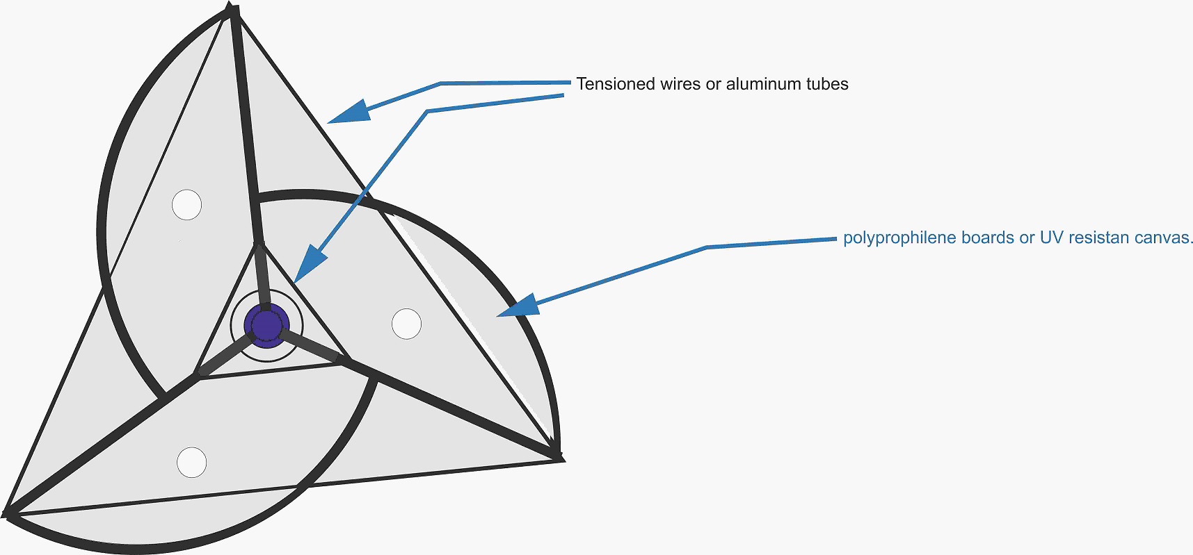
15194-0


Adriaan Kragten

  • Hero Member
  • *****
  • Posts: 1158
  • Country: nl
Re: new axial design multirotor
« Reply #91 on: January 30, 2023, 11:08:08 AM »

It is the same thing that happens with horizontal turbines, if more blades are used they work with lower speed winds but with higher speed winds the turbulence between them makes them lose efficiency compared to models with only 3 blades.


This statement shows clearly that you don't know much about HAWT's. You should study chapter 4.3 and the part about the number of blades B in chapter 5.2 of my report KD 35. In chapter 4.3, I give four reasons why the real Cp is lower than the Betz coefficient. Figure 4.3 shows that the number of blades has only a small influence on the Cp if you have three or more blades. Figure 4.2 shows that wake rotation has the largest negative influence on the Cp for rotors with a low design tip speed ratio. Rotors with a low design tip speed ratio have many blades to prevent that the needed chord becomes very large. Turbulence in the wind has no stronger negative influence on rotors will many blades than on rotors with three blades. Figures 4.5 up to 4.11 show that airfoil drag has the largest negative influence on the Cp for medium and high design tip speed ratios. The minumum Cd/Cl ratio for normal airfoils depend very much on the Reynolds number. A small 2-bladed rotor can perform even better at low wind speeds than a 3-bladed rotor of the same diameter and design tip speed ratio because the positive effect of a higher Reynolds number due to a larger chord is stronger than the negative effect of having one blade less. So it isn't true that rotors with many blades work better at low wind speeds.

Rotors with many blades are normally only used if a large starting torque coefficient is wanted like for rotors which drive a single acting piston pump. Those rotors rotor have a low design tip speed ratio of about 1.2 resulting in strong losses due to wake rotation. Savonius rotors also have a low design tip speed ratio and therefore a relatively high torque level and so the losses due to wake rotation are also high. This is also a reason for the low maximum Cp. There are small electricity generating wind turbines with 5-bladed rotors available on the market. These rotors have absolutely a lower maximum Cp than 3-bladed rotors with the same rotor diameter and design tip speed ratio. People who have designed those rotors have never heard of the Reynolds number. Using five blades may only look better than using three or two blades. 
« Last Edit: January 30, 2023, 03:35:15 PM by Adriaan Kragten »

JW

  • Development Manager
  • Super Hero Member Plus
  • *****
  • Posts: 4049
  • Country: us
    • Flashsteam.com
Re: new axial design multirotor
« Reply #92 on: January 30, 2023, 12:08:04 PM »
Quote from: leviatan
Very  interesting way to produce a ring without a massive quantity of steel.
About the end plates i considered that point, at this moment It's not my most important concern.
I dont know if i will use resistant UV canvas to save weight or the same material of the blades and to live with that extra weight.

The only other way to do it would be with a lathe and a C2 Carbide bit. I have a lot of experience with manual lathes. a 20 inch swing is pretty big not realistic for this its best to use hand tools.

MagnetJuice

  • Hero Member
  • *****
  • Posts: 558
  • Country: ca
Re: new axial design multirotor
« Reply #93 on: January 30, 2023, 08:14:38 PM »
JW, those are interesting ways to hold the pieces together. I don’t do welding; I take my jobs to a shop. I do the easy work.  :D

I was just thinking that the top plate could be attached to the bottom of the turbine with screws. Maybe there are better ways.

Here is the bottom plate. If there are other welders here, maybe they can suggest other ideas. leviatan wants it to be as light as possible.


15196-0


What can I do TODAY that would make TOMORROW a better world?

JW

  • Development Manager
  • Super Hero Member Plus
  • *****
  • Posts: 4049
  • Country: us
    • Flashsteam.com
Re: new axial design multirotor
« Reply #94 on: January 30, 2023, 08:26:07 PM »
The problem is that you have a lot of individual pieces. You would have to tack weld then drill and tap them with screws, then cut the tack welds. But yeah you could not weld to the magnet period. I see.

Actually you guys don't like welding that's fine, but you could fasten to the center of each individual "link" or magnet but you still would have to epoxy the mags to the type of rotor you have there. Unless your going to drill through the magnets your using somehow. What type of magnets are you planning to use. This could be a cheap construction design which isn't a bad idea.

Often necessity is the mother of invention what this means to the lay reader is. You find something in a scrap pile take it apart and often times you work with what you have. So if what you have has tonns of magnets in it of the same type you design something with what you have. but one has to understand theory of the chosen device. The problem that often occurs is that magnets with angular cuts to its perimeter are hard to alternate backwards and forwards to get alternating fields. Even so there are ways to do it, compare the OD of similar size square and circle magnets with the same thickness. You do need some type of back ring to complete the magnetic circuit on that plane if the individual pieces have an air gap of any size it wont work.

Huh even with an air gap on the sides it would work. Its best to allow for comprise its hard to do that I know. For such a thing probabally wouldnt matter because to reaching field depth/thicknees would be small either way.

The weight if the coils or stator copper would be small mostly in such a design. The big NEO magnets field has a greater depth of penetration of the copper coils so that they can actually make a more useful output. So yea it would work but the NET output power would be low.
« Last Edit: January 30, 2023, 08:57:07 PM by JW »

MagnetJuice

  • Hero Member
  • *****
  • Posts: 558
  • Country: ca
Re: new axial design multirotor
« Reply #95 on: January 30, 2023, 08:54:25 PM »
Either of these two magnets would work. I have a preference for the one with two holes, because there is less chance of it moving if the screw gets loose.

15197-0

What can I do TODAY that would make TOMORROW a better world?

JW

  • Development Manager
  • Super Hero Member Plus
  • *****
  • Posts: 4049
  • Country: us
    • Flashsteam.com
Re: new axial design multirotor
« Reply #96 on: January 30, 2023, 09:03:59 PM »
Yeah now those magnets look useful. I remember I was designing something years ago and the rep from the magnet company angrily told me you cant drill thru magnets. There are ways to get holes in them but that's not it. He then said and unless you need over a hundred cant do it that way either. I think a single chamfer is negligible also. You will need to flip the magnets as they are arranged side by side to alternate a staggered field polarity. One of the fasteners is going to protrude on the opposite side. With moving parts there can be interference/crash since the moving surfaces need to be as close as possible.

Also to consider the heavier the generating copper conductor is vulnerable to eddy currents which will overheat the conductor depending on rotating RPM in short order. Same with thinner conductors less current compacity. I have a utility Patent on a linier direct injection valve used to run a 4cycle piston engine "four-cycle steam" I solve part of the problem with both a primary and secondary mechanical stops to throttle the engine. This is an important configuration because of the benefit of compression ratio in the engine system. Believe me when your dealing with the USPTO you have to explain everything very well there constantly looking for "getyas and gotchaws"

The non moving actuator coil was wound with 1/8th copper tubing wrapped in a special fiberglass masking tape from Cotronics INC. I used a auto-type of 12 volt fuelpump to pump distilled water thru the center of the conductor. It carried 300AMPS @ 12volts constantly during its pulse schedule which was fixed. I used an array of solidstate relays mounted to a aluminum heat sink which used a SCR on the output of each one (they were connected in a parallel circuit independently with a common ground) and to protect the mosfets from the back voltage EMF generated by the coils impendence. None of theses construction details was listed in any of the patents because this is considered obvious. 
« Last Edit: January 30, 2023, 10:17:40 PM by JW »

MagnetJuice

  • Hero Member
  • *****
  • Posts: 558
  • Country: ca
Re: new axial design multirotor
« Reply #97 on: January 30, 2023, 10:25:35 PM »
I think that now is a good time to post this, as this historical accident has not been corrected yet.

This quote is from a book by Gary Johnson that I purchased long ago:

"The efficiency curves for the Savonius and the American Multiblade have been known for
a long time[6, 10]. Unfortunately, the labels on the two curves were accidentally interchanged
in some key publication in recent years, with the result that many authors have used an
erroneous set of curves in their writing. This historical accident will probably take years to
correct."


            Wind Energy Systems by Dr. Gary L. Johnson October 10, 2006

Here are the correct and incorrect charts:

What can I do TODAY that would make TOMORROW a better world?

Adriaan Kragten

  • Hero Member
  • *****
  • Posts: 1158
  • Country: nl
Re: new axial design multirotor
« Reply #98 on: January 31, 2023, 03:51:14 AM »
And so MagnetJuice continues to promote that a Savonius rotor can have a maximum Cp of more than 0.3 which is absolutely not true. I don't know the origin of the curve for the Savonius rotor as given in the graph but it might come from Savonius himself as he has measured a maximum Cp of 0.31. However, he has used a wind tunnel which was much too small for the geometry of the Savonius rotor and then you get tunnel blockage resulting in a very strong increase of the maximum Cp. You should read my report KD 599 and especially chapter 2.8.

Traditional multibladed rotors are not designed to have a high maximum Cp but to have a high starting torque coefficient because they are used to drive a single acting piston pump which has a very high peak torque. Most of those rotors were designed long ago when the aerodynamic theory as developed by Betz and Glauwert was not available. But if this theory, as given in my report KD 35, would be used for a multibladed rotor with a design tip speed ratio of 1.2, it is possible to design a rotor with a maximum Cp of more than 0.3. So even if the indication for the two curves in the given graph would be interchanged, the wrong indication for the Savonius rotor is best in accordance with the reality.

I have worked for 15 years at the University of Technology Eindhoven and have designed many water pumping windmills for developing countries. We have investigated multibladed rotors of traditional water pumping windmills but never I saw a correctly measured Cp-lambda curve of such a rotor. We have performed wind tunnel measurements for 6- and 8-bladed rotors with design tip speed ratios in between 1.5 and 2. We have measured a maximum Cp of 0.39 for lambda = 2 for the 6-bladed CWD 2740 rotor (see report KD 696). So assuming that a traditional a multi bladed rotor will have a maximum Cp of only 0.15 at a tip speed ratio of 0.9 is very unlikely. I think that the origin of that curve is the result of someones imagination.
« Last Edit: February 01, 2023, 02:12:55 AM by Adriaan Kragten »