Day two of the alternator assembly was supposed to be the day for checking small details, fixing them and then to try to take some meaningfull measurements.
First I needed to do something about the gap. When the alternator was first assembled, I didn't really have a good method for measureing the gap between the magnets.
A couple of diss-assembly runs and I finally conculuded that I need a spacer inbetween the magnet plates. Double nutting hasn't proved to be a very good method.
I seen a post by Dave B showing some spacers and I think that would be the best route.
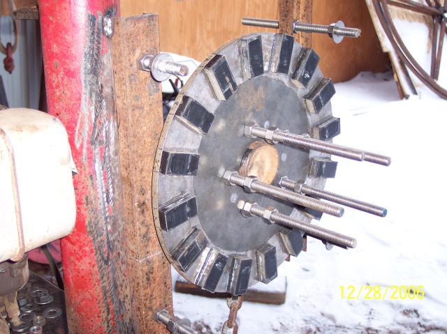
I was in the process of double nutting the all-thread here to set the air gap between the magnets, and currently I'm in the process of building the spacers.
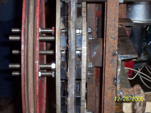
I was trying to get a look at the uneven gap in this picture but it's hard to see it here.
the pulley to the left in the picture was installed to run the alternator with an 8hp Briggs.
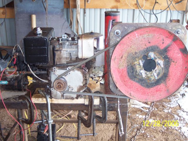
Here you can see the 8hp Briggs engine we used to turn the alternator.
With the pulley system in place we ended up with about 253 rpm on the alternator.
Under the table in the lower left of the picture you can see the 12V battery we used during the testing process.
On the table to the far left you can see the 12V starter motor we used to load the system.
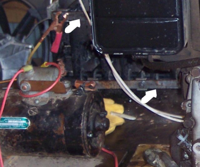
The rectifier is setting behind the engine and now has some steel bars to connect the diodes for the positive and negative terminals. (Much cleaner than the day before!)
The starter motor drew about 39 amps while running. The alternator's amperage output was in the neiborhood of 7 amps while the stater motor was running.
You could hardly tell there was a load on the alternator at 7amps. There was probably a drop of about 50 rpm on the engine while under load from the starter.
By the end of the day (if my math was correct) we ended up with 12VDC @ 122rpm.
So we weren't too far off Hugh's data which said cut-in occurs at 120rpm.
The total gap between the magnets was finally set to about .700". We used a depth mic on the double nut to the magnet plate.
Incidentally, the tilt angle on this alternator is going to be changed to about 6 degrees. I learned from my other diary posts, the angle was a little steep at 4 degrees. A bit of refigureing conculded 6 degrees would give me about 12" from blade tip to tower for clearance. All I really need to do is place an 1/8", wedge shaped shim under the bottom of the hub.
Well, that was day two. I feel like the project so far is a success, and I'm looking forward to the day when she finally starts flying.
The blades are being constructed out of laminated pine boards. So far I have built two blades. The first was constructed from one solid piece of full demension 2x8 pine, and the second was built from a laminated 2x8 board.
The laminate is by far the best choice so the rest will be built using that method.
Wil
