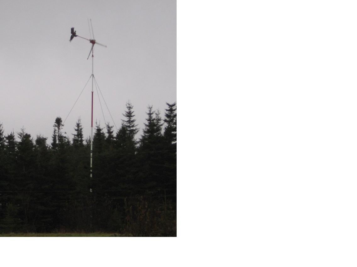
Hi, Gang! I'm a virgin... well to RE anyway, and I have just completed the
first phase of my Wind Turbine project. Do you like my bird? My wife carefully
painted this ring-necked pheasant, took two days. Thanks Sheryl.
I have been following all of your postings and experiences for over a year now,
and I have learnt an incredible amount about three-phase permanent-magnet
machines.
I come from a large family including nine brothers, most of whom are tradesman.
With their help, and many of our friends, I have collected most of the parts
required to build my wind turbine at a cost of about $1500 so far. This is my
story...
My goal was to build a wind turbine capable of powering my summer-home in Maces
Bay (Point Lepreau area, southern New Brunswick, Canada), and to finally be
free of the monthly power-bill. After acquiring the knowledge I needed to
proceed, and collecting the initial parts, I started construction...
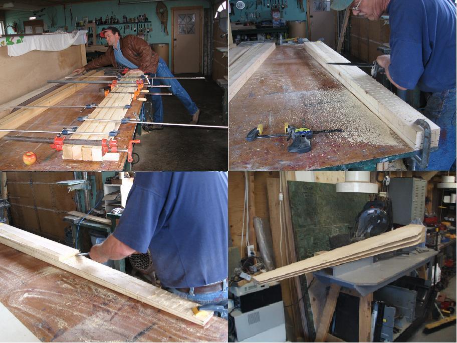
My wife's Stepfather helped with the blades which are constructed from laminated
Eastern-cedar. The blanks measure 7.5 by 2.25inches and seven feet long. They
weighed six pounds each when complete (I used my wife's food scale to measure).
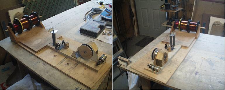
I built this coil winder for the project, and it worked very well. I added the
gear-head motor to wind my guitar pick-ups, this helps to justify the construction
effort (I tinker a bit with building electric guitars as a hobby).
As you should be able to see, there is a set of vertical pinch-rollers followed
by a set of horizontal pins, and finally a brass guide to keep the two-in-hand
wires fed close together on the form as you wind with a wrench. This system
nicely removes any kinks in the wire, as well. The mandrel is simply a peace of
hardwood that can quickly be substituted for any shape and size to yield the
desired coil.
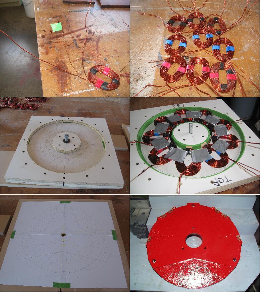
After winding the coils for a basic 9/12 machine, I built this mould. You can
see the CAD drawing of the stator imbedded into the bottom of the mould, and on
the lid. I designed the entire machine with a CAD package for CAM with a
water-jet, and also for accurate layout and drilling of the Stator. This
proved to be worth while, as the assembly of my alternator was slick! I allowed a 1/8th inch tolerance around each coil to compensate for any movement when the lid was clamped on the mold. You may be able to see a smaller 24awg wire wound into(embedded) the first coil picture. I wanted to build several experimental features into my first wind turbine for later testing. I intend to use this 24awg coil as a "sensor", un-hindered by load, to drive a Star-Delta switch and monitoring station. You will see that I ran a separate 14/3 control wire down the tower to connect this feature to the control circuitry. The stator was cast with a 1-2-2.5 part mixture of poly-resin, talc, and triple-aught silica sand, respectively. I
decide to "go on a limb" after an un-scientific experiment, where I mixed a
six-inch disc, half-inch thick, of traditional mixture of poly and talc, then a
disc of the chosen mixture. I placed each disc on a pre-heated hot-plate, and
placed a hand on each and waited for them to get warm. The silica mixture got
warm in less than half the time the traditional did - good heat transfer!
Another observation was the rigidity of the silica mixture, it was very hard, and stood several more heavy blows with a 20oz hammer. The silica also mixed easier than the talc alone. Probably because it does not tend to lump like talc and assists in separating the talc when stirred. I found only one undesirable effect of the silica - it is hard on drill-bits! The last picture shows the finished
stator (15" x 5/8") with the bracket overlaid showing the precision obtained at
the drill holes. The paint used was epoxy-based. For the curious, I tested the
resistance of each coil using a PK-Precision current source and measured the
voltage-drop. Ohm's law applied, ~.04 ohms per coil, which is enforced by 42
turns (approximately 30 feet per coil), two-in-hand 14awg copper(.0025ohms/foot
x 30 /2). Each phase also measured .11 Ohms after the stator came out of the mold.
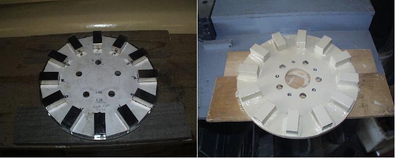
Aiming for a 24volt machine, I decided to go with doubling the flux density
with 1x1x2 Neos, as all water-jet CAM parts were cut from half inch plate
(plenty of strength as well as the added fyl-wheel action obtained from the
weight). The rotors are 12.5 inches in diameter. The white template is made from common hard-board furniture-backing. A good friend in the automotive industry donated a special body-panel adhesive, new on the market, which yields 1000lbs/inch shearing strength, better sealing quality, and much wider temperature tolerance than the traditional panel adhesive. I found it easy to work with. It also stands firm until cured, allowing the welded-look around the edge of each magnet in the last picture. I do not think it is necessary to submerse the magnets in epoxy, and I want good centrifugal-fan action for cooling. For a complete seal, I coated the entire magnet-rotor in epoxy paint. This is the front-rotor, notice the threaded-hole for jacking.
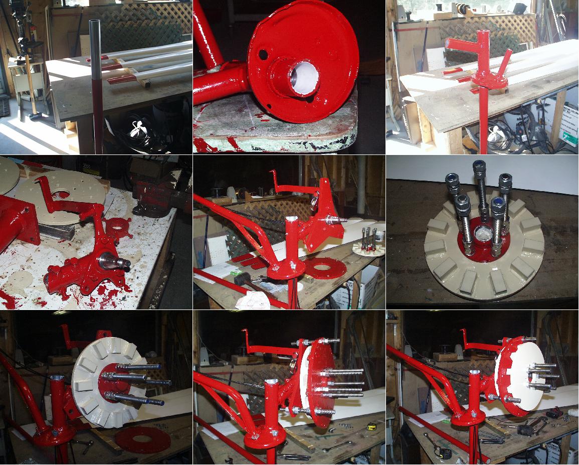
All parts are coated with epoxy paint as the weather conditions here on the
Fundy Bay are always very windy, adding sea salt-corrosion to the list of
potential problems for a project of this magnitude. The threaded rod, nuts, and
washers are 5/8 UNC stainless. The first picture shows the Yaw-stand, made
from 36 inches of 1.25inch sch80 DOM pipe (seamless) with a polished finish to
act as the race for a Teflon bushing installed in the Yaw mount shown in the
2nd picture. There is also a Teflon bushing in the top along with a stainless
thrush washer. In the subsequent pictures you will notice several points of
design that are deferent from the norm. I wanted to experiment with some ideas, so the proto-type seamed as good a time as any to try them out. In the 4th picture
you will see that I opted to 'step back in time' and use a automotive strut
(Volvo of course). I like the thought of recycling. A lot of parts in this
project are of "junk-box" origin. I have designed the tail-boom so the
furled-stop is the flat-bar attached to the tie-rod arm protruding from the
back of the spindle assembly, and the rest-stop is a air-craft cable (double for
safety) anchored using one of the original lower-ball joint bolts and the other
end bolted to the boom where the length of the cable allowed a 90 deg position
from the blades. This effort was to keep the tail-boom pivot a solid pipe over
a one-inch cold-rolled pin to lessen fatigue. A large washer welded to the
pivot-pipe allows for a mating 1/4inch bolt, washer and locknut to secure the
boom from lifting off the pivot-pin. I have decided to use six half-inch UNF
bolts to fasten the spindle assembly to the Yaw. This allows for tilt
adjustment for blade clearance, as well as furl adjustment by positioning the
alternator between five and eight inches from the Yaw stand. The stator bracket
is gusset-shaped to take the turning forces when Current demand is high. The
last picture you can see two sets of double air-craft cables going down from
the strut's coil-spring flange. These cables act in unison as a torsion system
to limit the number of 360 deg turns the machine can swivel on the tower before
twisting the aircraft cables tight around the Yaw stand. The locking collar is
the ring (with four 5/16 bolts at 90deg) in the background of the 4th picture.
This is what holds the opposite ends of the four torsion-cables to the Yaw
stand and allows for maximum turns adjustment by sliding the color up or down
the 36 inch yaw stand. I am not at my summer home for weeks at a time, so this torsion system should ensure my 6/3 power cable does not twist too far. I added grease fittings for both pivot points, and a pulley was added for a manual-furl cable.
You may have already guessed the short-comings of this assembly - the tail-boom
flange! I have rectified this weak point, and will add pictures near the end
of this post.
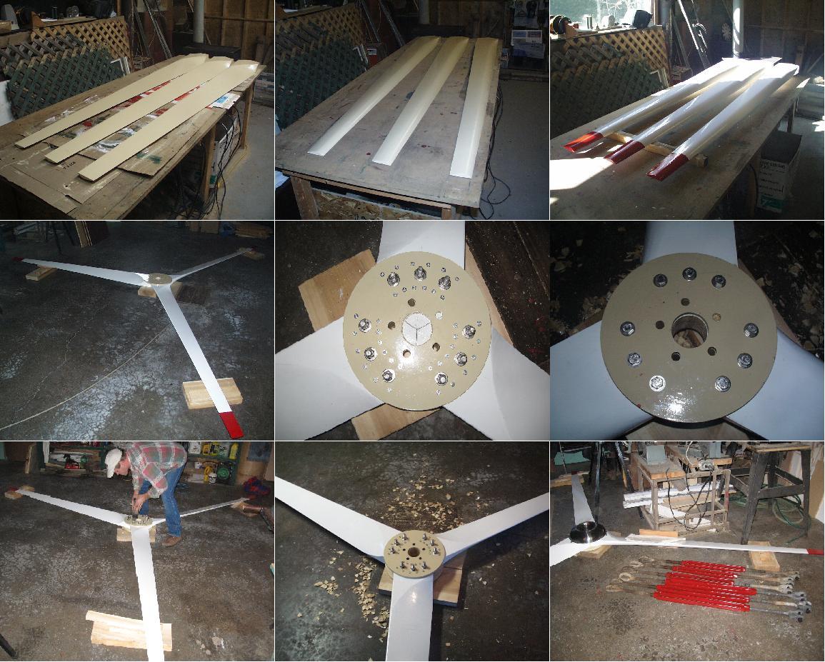
Next is the Bade assembly. I wanted the ability to test double stator design
in the future, so I designed the blades larger than necessary (7 feet), paying
particular attention to the airfoil and cord thickness hoping for good
performance/speed for the initial single-stator alternator, as well as strength
to drive a double the double. Again, epoxy paint was used. The blade-hub was
cut from the same half inch plate with water-jet CAM. This added even more
weight for flywheel action to buffer gusts of wind. The main reason for
using heavy plate here is for the flux path of the front rotor (magnets on both
sides), and mounting magnets to the back side of the blade-hub for the future
second stator design. This makes the modifications easier as the existing
design is ready for these magnets and stator, including the strength of the stator bracket and length of the threaded-rod. The CAD design of the rear blade-hub and bolt placement incorporates this modification. Another feature is the 2.5 inch hole in the center of the blade assembly to aid in cooling the alternator. A 13 inch stainless bowl (with a smaller stainless bowl concaved into it), mounted as a
nosecone concentrates the oncoming wind into the center hole creating a
high-pressure area, just before the low-pressure area of the centrifugal fan
action of the magnet rotors, resulting in very good air flow around the stator.
A small stainless grill was riveted to the concaved bowl base to stop any
debris from getting into the alternator. My one concern with this design is ice
build-up from the venturi action of the orifice (time will tell). The last
picture shows the cone installed as well as the one-inch turnbuckles I got from
salvage. The blades weighed in at 6lbs 4oz each, painted. Static balancing
was bang-on (I suspended blade assembly on plumb-wire from garage ceiling).
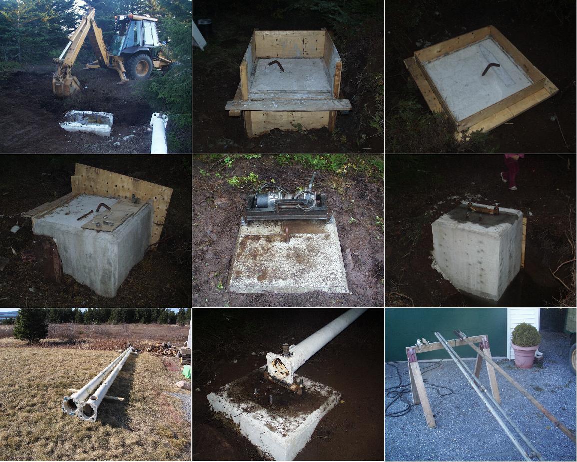
Now for the dead-men, tower-base, and supporting structure. My wife's father
owns a heavy equipment company, and he donated the time to dig the holes down
to ledge and backfill after the concrete was set. I quilled the ledge with
rebar and set plenty of rebar in the concrete. I use one-inch foundation pins
as the anchors for the half-inch guy-wires. The tower is a tilt-up style built
on top of a 25-foot industrial light-pole donated by a good friend. I had a
lone of the 4-ton winch from another good friend, which mounts nicely on the
dead-man in the 3rd picture where you can see the hunk of the ledge close to the
surface. The gin pole coupling was welded to the cast-steel base of the tower,
which allows for removal of the gin assembly after the machine is raised. The 20-foot gin pole and brace is shown in the last picture.
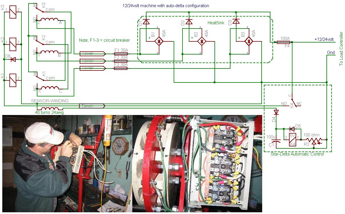
As mentioned earlier, I wanted to experiment with Delta switching in
high winds (which we get a lot of), so here is my design. This system defaults to Star (Wye). It is a good time to point out that the mechanical air gap has been set to 3/32nd of an inch resulting in a total displacement of opposing magnets to around 7/8 inch. The closest point between adjacent magnets (same rotor) is 1.1inch apart, as I am trying to get the most out of the 1inch thick N40 magnets... concentrating the flux through the stator.
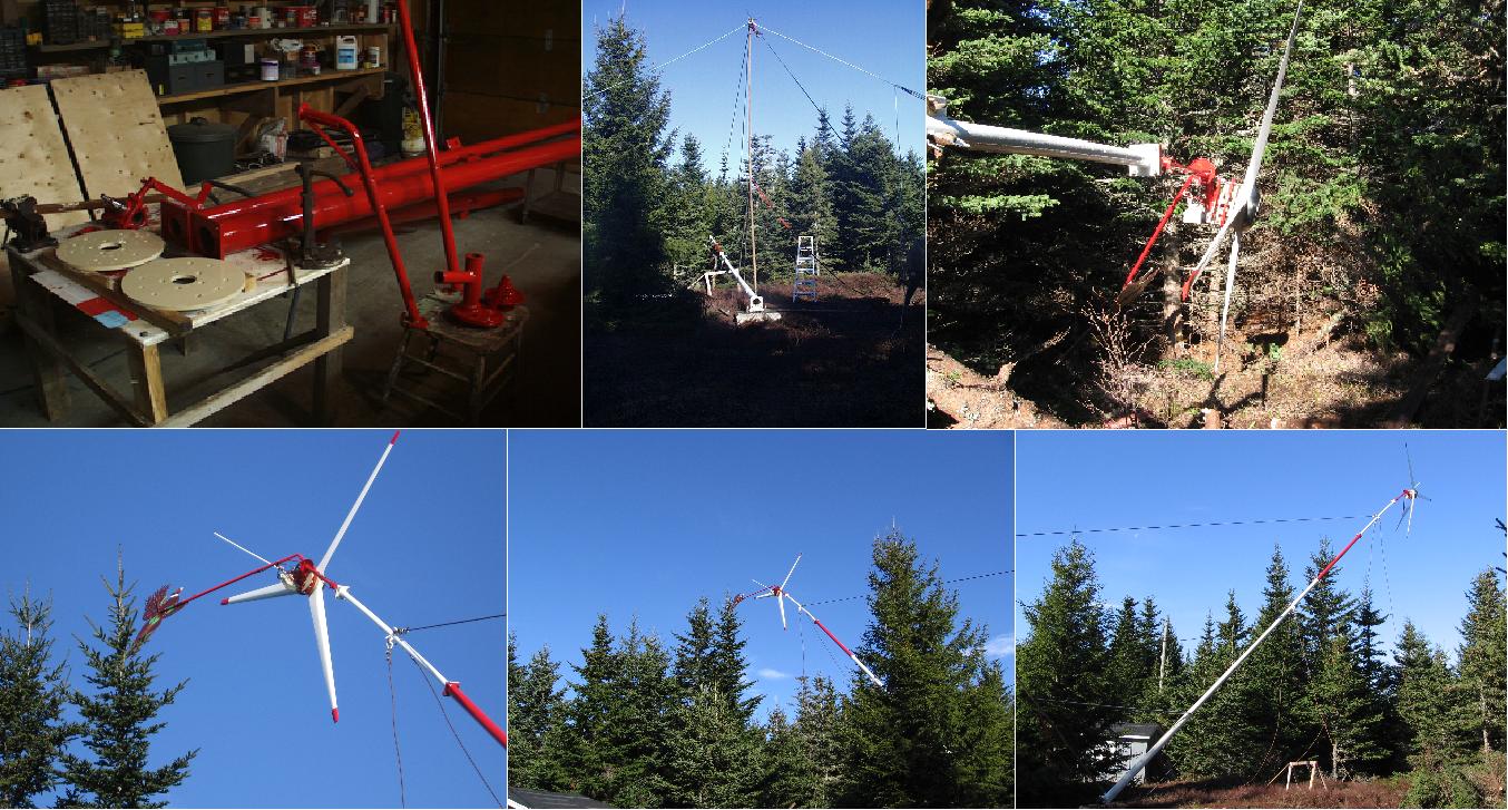
The moment of truth has arrived. After a year of planning, I am finally ready
to put my bird in the sky! The total tower is built to disassemble by way of
four hardened 5/8 bolts at each 10-foot junction of 4inch sch40 pipe. The
joint flanges were cut with the same water jet job of half inch plate. The top
section of pipe is 2.5 inch sch40 that I got from salvage, and you can see it
flex when the tower is horizontal. This did bend or kink, when the tower was
completely erect, it was solid and straight. However, I decided to replace this section with 4inch sch40 the
next time I lower the turbine.
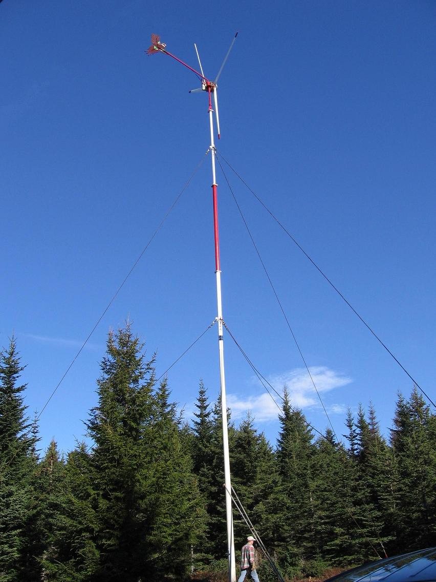
Success, as I finish adjusting the turnbuckles. Isn't it prurdy? The total
height of the tower is 53 feet, and the height to the tip of the lightning-Rod is
60 feet. Notice the torsion system limiting the machine to one turn (this is a
test run) pointing ESE when the wind is from the South. The Wire cables have
an inherent ability to provide a cushion-effect at the stops, so the limits are
not abrupt.
It was flying for a week, with excellent heat from a home-made three-phase
heater, when it experience the common Fundy-Bay winds... the tail-boob flexed enough until the flange cracked and my bird started flying low. I had to lower it (in high winds!!!), afraid the tail may crash into the blades. Since then I built
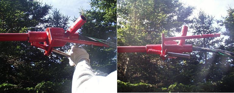
a new yaw assembly and added a better support to the tail-boom. I also
replaced the top ten foot section with 4inch sch40. I have not completed the DC
or Inversion phases of the project yet, so I have very little performance data
to pass along, however I could not stall the blades using six-foot booster
cables (10awg, cheap) as a dead-short in 25 mile per hour winds. Believe-it, or
not, the insulation on the cables got hot and soft very quickly!
The following are pictures of the install of the new yaw and flange.
Then disaster!
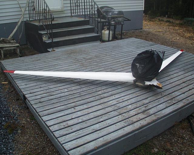
I was flirting with disaster by being a lazy-man and cutting corners on the
gin pole side supports. By not installing a small dead-man anchor to the sides
of the gin pole, inline with the hinge for tie-downs, I tempted faith one too many times! I had a man steady the ropes with pulleys tied to trees at 45deg in front of the gin pole, which required constant adjustment for the change in distance as the tower was raised. One of the men over compensated and reached the critical
point of no return. The machine came down with such force, one blade exploded
into tooth-picks! I have not mustered the nerve to inspect the alternator for
damage yet. Suppose I will pick away at the repairs throughout the winter. I
am sad but not broken. Sometimes these things have a way of being necessary...
A note to all new-comers, please don't get hasty and rush to the finish-line.
Cheers!
