Author Topic: Starting to get going!  (Read 4827 times)

0 Members and 1 Guest are viewing this topic.

elt

  • Sr. Member
  • ****
  • Posts: 328
Starting to get going!
« on: September 05, 2006, 05:41:54 PM »
Wow that was fast! I sent the dxf file for the metal parts off last Monday, they (mostly) came today. (Eight days.) Mostly came... I got the "big" pieces but not the cap for the turret and not the angle used to hang the tail. I sent off an email to see what's up with them.


The rotors are 11" diameter and 3/8" thick. I put on of the 1x2x.5 inch N42 magnets on to show size. It's amazing how the disk blocks the magnetism on the other side. I can feel a very tiny small pull on my screwdriver when I'm about 1/4" from the outer edge but nothing at all from there on into the center. There certainly is some attraction once you get off the edge of the disk. IIRC, I've read of "flux leakage" off the edge. Some of the pics I've seen of rotors with round magnets have the magnets inset from the edge but the pics with rectangular magnets seem to have them placed right up to the edge of the disk; that's my plan for now as well.


Twentyfive magnets came Friday; I got one extra to play^H^H^H^H have as a spare.


The neo's are dangerous! I've been extremely careful and fortunate but my son's girlfriend got a blood blister when the magnet and pliers she was playing with pinched her hand, But it's fun to the point of being worth a little risk ;-) The most fun thing I've done so far is magnetized a 6" steel rule to the point where it points north like a compass, then from I can aim different faces of the neo at it and get it spinning like a top! Not sure I want all my tools and things magnetized though...


Unfortunately, I can't spend but a little bit of time building every day. [sigh] I'll post more pics once I get the disks cleaned up and the holes for the jack screws tapped.


Thanks to everyone for the help in getting me going!


- Ed.

« Last Edit: September 05, 2006, 05:41:54 PM by (unknown) »

elt

  • Sr. Member
  • ****
  • Posts: 328
Re: Starting to get going!
« Reply #1 on: September 06, 2006, 02:15:45 PM »
Day 2 -


It's not obvious in my drawings but the section of the hub mounting plate that connects to the yaw bearing pipe is curved. I calculated the curve so that the weld line would be flush with the pipe when the hub mounting plate was tilted the 4º that Hugh recommends in his booklet.


I used some nuts and bolts to set the angle and height relative to the pipe and took it it too my welder guy to weld. I'll get that tomorrow.


Then I tapped the 24 holes for the 10-24 screws to hold the magnets in place and the four 1/2-13 holes for the jacking screws. I tried to assemble for a dry fitting but the 12 mm holes called for in the plans were too small for me to get the parts together so I enlarged the holes to a half inch. (I would have used a 31/64" but that bit in my index set was bent about 3/32 inch! Well get what you pay for and I paid for an 8 dollar Chinese index set at a truckload tool sale...)


Well, there it is, I don't think the 1/2" holes are too sloppy; I'll just take care to check that it's balanced when it goes together.


- Ed.

« Last Edit: September 06, 2006, 02:15:45 PM by elt »

elt

  • Sr. Member
  • ****
  • Posts: 328
Re: Starting to get going!
« Reply #2 on: September 07, 2006, 01:24:56 PM »
Day 3 -


Hub mounting plate and yaw bearing pipe welded together at 4º angle

« Last Edit: September 07, 2006, 01:24:56 PM by elt »

elt

  • Sr. Member
  • ****
  • Posts: 328
My coil wider
« Reply #3 on: September 18, 2006, 02:46:06 PM »
Day 4 -


Well, it's taken a week and a half to get to day four and build something else; the biggest holdup was trying to finalize (unless I change my mind) the coil size. When I went into the shop to make it, I designed it on the fly to use what I had on hand. The only "trick" I used was to drill three larger pieces of wood at the same time so that all the holes lined up, then I separated them and cut the sides and center spreader to shape.


Here's a pic of the winder -


It has two "handles" right now. I didn't know how long I wanted them so cut a long piece with different lengths sticking out from center. Once I decide I'll trim one end or the other and put a spinner knob on the one that's left.


You can see the simple drive mechanism when I take off the 3/8" nut -


The handle is drilled out with two 5/16" holes to engage the heads of a pair of 10-32 socket cap screws.


You can see in the "exploded" view -


- that the back side retainer has threaded inserts to mate with the 10-32 screws. I will only uses screws long enough to thread into those if the side pieces bow out while winding the coil; otherwise, shorter screws make taking the winder apart a lot faster...


There's no lock washer or lock nut in the assembly. Turning the winder clockwise tends to keep the front nut on tight enough so that the 3/8" bolt turns nicely on the nylon washer (under it's head) and in the bushing going through the mounting stick. Once the coil is taped off, turning it counter clockwise loosen up the front nut enough to taking it off by hand.


I don't have my magnet wire yet though I'm in on an ebay auction and have my fingers crossed... I did strip some short pieces of #12 romex so that I could test it -


Well, that was a real PITA winding the romex; I sure hope the #13 magnet wire has a lot softer anneal!


- Ed.

« Last Edit: September 18, 2006, 02:46:06 PM by elt »

elt

  • Sr. Member
  • ****
  • Posts: 328
First coil wound
« Reply #4 on: September 26, 2006, 01:38:30 PM »
Day 5 -


Well, I didn't win the first wire auction I was in but I did find a 10+ pound spool of #15 wire at a nice "buy it now" offering; that came yesterday.


"The plan" is 63 turns of #15 two in hand. With only one spool, I decided to wind out two lengths and respool them together. I measured out 50 feet, bent it back on itself and ran out another 50 feet. I rewound the wire (two in hand) around a small pail.


I put a gallon varnish can under the pail for it to spin on and it unwound very well! Just once a coil unlooped from the top rather than unwinding, I didn't see happen because my eyes were glued to the coil forming and when the kink hit my hand I used ungentlemanly language... next time I'll put a board on top of the pail to stop the wire from coming off the top and I don't think I'll have that problem again. But before that happened...


I'd given some thought on how to get the coil start out of the center. Because I'd planned my coil a little on the thick side (.6") I didn't want to add any more to the thickness because of the start wires coming under the formed coil. I searched the board and found Flux's technique of using thin copper strips to bring the start out and that sounded like a really good idea. In the end I decided on something simpler: I just wound the start wire into the outside of the coil -


I realized that this would make the outside of coil a little wider but it doesn't seem to me that that really matters...


I checked the coil width as I wound and stopped when I got to the .75" with (on the inside corners of the coil) that my layout allowed. I only got 60 turns, about 45 feet, rather than 63 turns I was shooting for. Well, 63 turns would have been "perfect" technique; I didn't really expect perfect.


I might have wound another layer on but I was a nit over my .75 width budget already and since I have enough wire to throw this coil away if I have to, I decided that I'11 mount this one up and see what 60 turns do... not today, though, I'm still waiting for the Loctite that I'll use to attach the neos so the rotor are still waiting to be made.


 - Ed.

« Last Edit: September 26, 2006, 01:38:30 PM by elt »

ghurd

  • Super Hero Member Plus
  • *******
  • Posts: 8059
Re: First coil wound
« Reply #5 on: September 26, 2006, 02:06:05 PM »
Don't throw it away!

At least use it as a test coil.  It may be just what you needed.


I expect you didn't get a response because there is nothing horribly wrong. :)

Looks better than anything I ever did.

G-

« Last Edit: September 26, 2006, 02:06:05 PM by ghurd »
www.ghurd.info<<<-----Information on my Controller

elt

  • Sr. Member
  • ****
  • Posts: 328
9 Coils wound, started on stator mold
« Reply #6 on: December 10, 2006, 03:33:30 PM »
I guess this would be "Day 7" in working-on-mill days. I've been swamped with building telescopes and hadn't made much progress on my mill but I managed to get a little time in on the project yesterday and today... got my coils wound and stator mold almost ready for sealing -


I got my vinyl ester and fillers in from US Composites so I hope to cast the stator this week. My plan is to vacuum bag the coils and try to draw in a mix of resin and aluminum trihydrate to pot them and then fill and cast the rest of the mold with a mix of resin, chopped strand a little more aluminum trihydrate...


 - Ed.

« Last Edit: December 10, 2006, 03:33:30 PM by elt »

elt

  • Sr. Member
  • ****
  • Posts: 328
I cast my stator!!!
« Reply #7 on: December 14, 2006, 04:02:55 PM »
Days 8 and 9:


I'm pretty excited how my stator turned out! It has a few surface blems but it looks like it's going to work out.


Here's some pics -


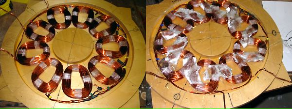
I wired the coils then tacked them together like Dan shows in his instructions. I took the coils out and soaked them in a 50/50 mix of resin and ATH; then I put them in a bag and pulled a vacuum.


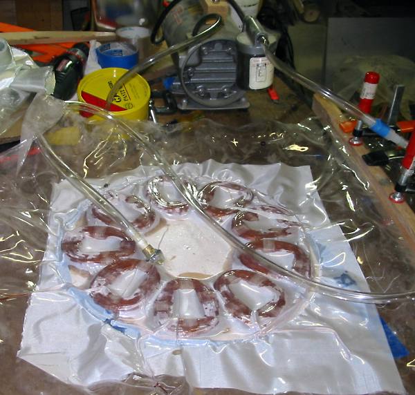
My theory is that when the vacuum is slowly released that the vacuum in the coils will suck in the resin... well, I read that that's how they oil emeralds (which infuses the cracks and flaws with oil so that it looks brighter.) My hope is that by getting the ATH in there that the coils will lose heat better.


I put another coat of wax on the mold and started to pour the stator, though "pour" isn't exactly how it went...


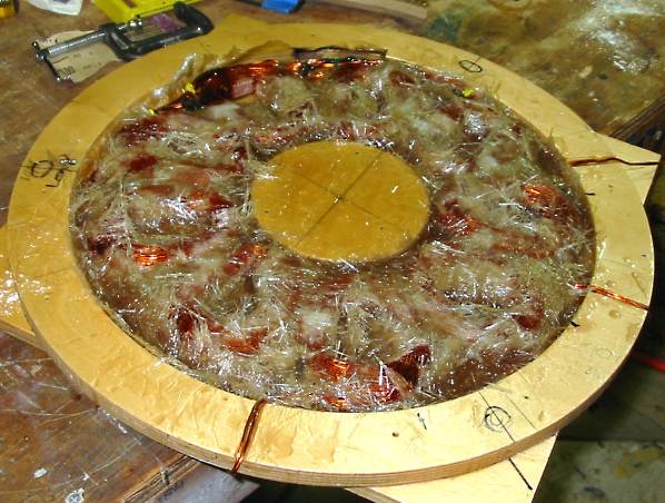
I poured in some resin, put in the fiber glass fabric then after saturating and smoothing out the fabric, I put the coils in. I mixed up a pint of resin, a cup of 1/2" chopped strand and a cup of AHT. (mix ratio 50/25/25) It was still a little soupy and would have taken some more chopped strand but it the chopped strand was longer and stringier than expected and I was concerned about getting all the crevices filled if I added more. At any rate, it certainly wouldn't "pour." I ended up using a paint stirring stick to scoop the mix into the mold and the end of the stick to push it down into the smaller areas... the picture is a little bit past half way through the pour... what a mess! Well next time I'll use 1/4" chopped strand, I think that will be easier going.


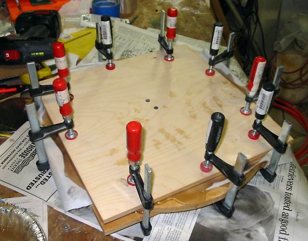
After I got the body of the mold filled, I poured on some resin (without additives) and put on the top piece of fabric. When it was clamped up I got a enough squeeze out that I felt like I had enough resin in there. I checked on it after an hour and the mold was nice and warm to the touch. After about four hours it was mostly cooled down so I thought that I'd pop it open.


Well that top came off very easily. The stator didn't pop out, though, and it didn't come out with a gentle thumping. I whacked and whacked; no good. I took a pry par to the mold and after I had the ring loosened, the stator finally fell out.


Here's a picture of the stator -


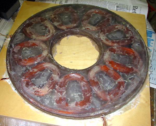
This is the "bottom" of the mold; you can see it's a little scalely where the resin mingled in with the wax. Eventually I'll scrape and sand and it and paint it. For now, though, I'll let it lay flat overnight, then I'll drill the holes for the mount tomorrow. I can't wait to get it in between the rotors and check the volts...


  - Ed.

« Last Edit: December 14, 2006, 04:02:55 PM by elt »

elt

  • Sr. Member
  • ****
  • Posts: 328
Re: I cast my stator!!!
« Reply #8 on: December 15, 2006, 03:37:18 PM »
Day 10 -


Here's a picture of the assembled alternator


... got to take it all apart now and do some painting!


- Ed.

« Last Edit: December 15, 2006, 03:37:18 PM by elt »

elt

  • Sr. Member
  • ****
  • Posts: 328
Initial progress on 10' blade set
« Reply #9 on: December 21, 2006, 05:55:22 PM »
Yesterday I cut the profile on a set of 10' DanB blades; today I cut and planed them to thickness.


This is my second set of blades. I did a set of the 7 footers from the windstuffnow's website before I figured out that I needed a 10' mill. After doing that set, I waited for a sale at Harbor Freight and bought a power planer; I think it's the best $30 I've ever spent! One bonus I hadn't thought of is the dust ports. Carving the 7 footers left me ankle deep in wood chips, now there's just a little dust from sanding... this set is going so much faster the 7' set did without the planer; I can see how a newbie like me might get a set done in a day (even if I am spreading it out a bit longer than that.)


- Ed.

« Last Edit: December 21, 2006, 05:55:22 PM by elt »

elt

  • Sr. Member
  • ****
  • Posts: 328
Re: Initial progress on 10' blade set
« Reply #10 on: December 23, 2006, 04:37:18 PM »
Third day working on the blades -


I cut the twist into the blades today; took about 1/2 hour per blade.


The power planer can't get all the way to the root so that has to be done a different way. I has a Sawsall so I gave that a try. It to took a bit to get the hang of cutting out the root ; the first one came out kind of ugly. This one wasn't too bad...


The belt sander smooths the rough cut out pretty quickly.


I'll work on the air foils tomorrow. There's an inconsistency in the Otherpower plans: Two diagrams show the blade thickness at r=30 inch as 1.125 inches. The third diagram (of the airfoils) shows the same station with a thickness of 1 inch. I'm guessing that the 1.125 inches is correct and have carved according.


 - Ed.

« Last Edit: December 23, 2006, 04:37:18 PM by elt »

elt

  • Sr. Member
  • ****
  • Posts: 328
Finished Otherpower-ish 10' blade set
« Reply #11 on: December 26, 2006, 04:12:37 PM »
I had the twist cut into the blades; before I carved the air foil a a fare amount of time to get both sides of the blades flat and all the thicknesses the same... about an extra 20 minutes per blade. I think that paid off because when they were done they were within three ounces of each other. (Averages about 3 pounds, 14 ounces per blade.)


I wrote Otherpower-"ish" because I modified the twist before I cut the air foil. It doesn't say in the Otherpower blade plans what the TSR of the blades is but Googling the board suggested that they are about TSR 6. I wanted about TSR 7. So I experimented with Alton's blade calculator page (http://www.alton-moore.net/wind_calculations.html) looking for what I hoped would be a simple mod to the blade.  


What I ended up with was taking about half of the 5/32" twist at the tip out. I marked about 2mm at the front side of the leading edge and drew a line about 20 inches. I re-planed the front flat to that line and blended it in with the existing twist. That gave me about 1.5 degrees at the tip and 3.5 degrees at 75%... pretty close to what Alton's page gives for a four station version of a TSR 7 blade.


That did make the tips thinner as well but coincidentally (or not!) they matched the 10mm thickness given by the blade calculator...


- Ed.

« Last Edit: December 26, 2006, 04:12:37 PM by elt »

elt

  • Sr. Member
  • ****
  • Posts: 328
Alternator, yawl bearing finished; pictures
« Reply #12 on: January 04, 2007, 08:36:40 PM »
I'm sealing the blades with epoxy. It's cool in shop so that's taking a bit of time. In the mean time, I've painted the alternator parts and yawl bearing -


The magnets are attached with an acrylic glue and a 10-32 bolt that goes most of the way through them. The magnets were then painted with three coats of epoxy to protected them from the weather and then the epoxy was sprayed with grass green enamel to protect it from UV.


I'll paint the blades white after they're sealed; I think it'll look pretty nice sitting up there in the air!


- Ed.

« Last Edit: January 04, 2007, 08:36:40 PM by elt »

RP

  • Hero Member
  • *****
  • Posts: 722
  • A dog with novelty teeth. What could go wrong?
Re: Alternator, yawl bearing finished; pictures
« Reply #13 on: January 04, 2007, 09:48:21 PM »
Elt,


Is that pipe fitting under the unit just for the test stand?

« Last Edit: January 04, 2007, 09:48:21 PM by RP »

elt

  • Sr. Member
  • ****
  • Posts: 328
Re: Alternator, yawl bearing finished; pictures
« Reply #14 on: January 05, 2007, 08:46:11 AM »
Yes, that's just part of the test stand; I was read the riot act on pipe fittings when I proposed this beasty ...


http://www.otherpower.com/images/scimages/6527/mount_1.jpg


... a shame though because the pipe fitting yawl bearing was so easy to make!


 - Ed.

« Last Edit: January 05, 2007, 08:46:11 AM by elt »