Hi All,
I've been learning a lot about wind-powered alternators and 3 phase power, and two basic instructions got me thinking about a solution that I haven't seen discussed anywhere.
First, there's the common mistake of placing a pair of coils in opposite rotation (one CW and one CCW) that causes them to cancel out each other's voltage.
Second, when setting up a 3-phase system, it is noted that the common ground will ideally always have zero voltage, or potential difference, because the sum of 3 sine waves 120° out of phase is always zero. (when they have equal freq. and amp.)
It occured to me that if a pair of stator coils had one coil rotate 90° out of phase then, regardless of rotor speed, a linear decrease in output voltage would be seen while maintaining the same frequency.
It seems to me that for the purposes of voltage regulation, dump loads, furling, etc. it would be better to use this method to simply reduce the load rather than divert the load to heating elements or mechanical braking methods.
I've seen discussion about dynamically increasing the air gap, but that provides an exponential decrease rather than linear - which is hard to make use of. Am I missing a basic principle here, or should this method work?
...and does anyone know if it's been tried?
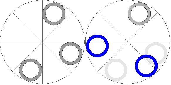
I've designed one for a three phase alternator, and the simplified picture below shows one way to do it for a set of 3 coils wired in series. (all in phase 1 of 3). The rotor here has 8 alternating magnets producing a full sine wave every 90°. The left position would render full output voltage, and the position on the right shows the fully moved coils in blue, where each of the three coils contributes a sine wave 120° out of phase with the others to produce a net of 0 from this set.
Thanks for your input,
-Masked