Author Topic: Diversion Controller Project  (Read 3362 times)

0 Members and 1 Guest are viewing this topic.

mtbandy

  • Jr. Member
  • **
  • Posts: 53
Diversion Controller Project
« on: May 17, 2009, 12:00:30 PM »
Hi all,


I thought some of you may be interested in my latest project which is now up and running. For a while I have wanted to build a better controller for my solar panels. I decided to build a diversion controller, simply because I wanted to see the excess power coming in on a sunny day! This has the added bonus that it could work with a wind turbine.


What separates this from 99% of other similar controllers I've seen is that it does not use 'bang-bang' control - instead it has a buck converter on the output to deliver a constant current to the dumpload, and a feedback loop controls the duty cycle of the converter. This means that the dumpload can be placed some distance from the battery bank, without causing RFI (for example, wiring could be several meters to a water heater).


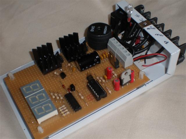
It is based around an Atmel AVR which runs the control loop, produces the PWM, and refreshes the display. There is a completely separate overvoltage 'catch' board, to disconnect the solar input by opening a relay (15v disconnect, 12.6v reconnect) that would only ever come into play if for some reason the dumpload failed.


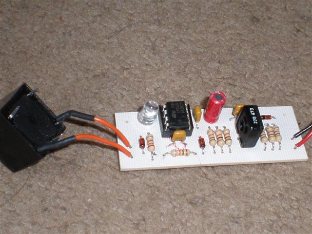
Overvoltage Disconnect Board


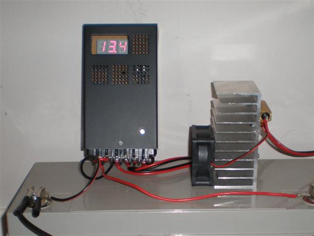
Hooked up for test with dumpload (2ohm resistor on heatsink). Been running for a week now


Currently, the controller is limited to a dumping current of only 8A, this is due to the size of the inductor. If this were beefed up, the controller could dump about 35A, limited by the size of the heatsinks. If anyone is interested, I will eventually post schematics, etc.

« Last Edit: May 17, 2009, 12:00:30 PM by (unknown) »

Boss

  • Hero Member
  • *****
  • Posts: 551
  • http://outfitnm.com
    • Outfit Renewable energy site
Re: Diversion Controller Project
« Reply #1 on: May 17, 2009, 09:37:12 AM »
Yes very interested, please show us the electronics. Good looking work

I like the LED read out too, at the moment I have my Fluke connected to my diversion controller, and an ammeter inline to the batteries, as well as another ammeter before the 650 watt UPS we are using as an inverter.

 
« Last Edit: May 17, 2009, 09:37:12 AM by (unknown) »
Brian Rodgers
My sustainable lifestyle site http://outfitnm.com no ads, not selling anything either

mab

  • Sr. Member
  • ****
  • Posts: 429
  • Country: wales
Re: Diversion Controller Project
« Reply #2 on: May 17, 2009, 12:02:42 PM »
Hi,


I'd be very interested too.


I've done something similar based on an MC34167 buck regulator, but it is limited to 5A as I'm using the internal power switch - that's adequate for the modest setup I have at the moment, but when I've built my big wind genny...


The advantage of this setup is that I can dump the surplus from my 24v battery/solar system into my 12v system with high efficiency - if there's 2 surplus amps coming into the 24v system It's converted into 4 amps going into the 12v battery.


I couldn't make my mind up over 12 or 24 volt systems so I've got both. :)


mab


130W solar array - runs the lights, PC, fridge & radio - what more do I need??


PS. One day I'll get organised (ha ha) and post a description of my system.

PPS. Many thanks to the regular posters on fieldlines - so far i've found answers to all my questions by searching old posts. :)

« Last Edit: May 17, 2009, 12:02:42 PM by (unknown) »

commanda

  • Hero Member
  • *****
  • Posts: 731
Re: Diversion Controller Project
« Reply #3 on: May 17, 2009, 02:47:19 PM »
I trust that the relay for the overvoltage solar disconnect draws it power direct from the solar panels and not the battery, so as not to present a phantom load on the battery?


Also, it's only a little extra code to implement a dual-state charger; much kinder to the SLA's I see you're using. Assuming you regularly reach full charge that is.


Looking forward to seeing circuit diagrams and code. Interested in where you got the enclosure from also.


Amanda

« Last Edit: May 17, 2009, 02:47:19 PM by (unknown) »

mtbandy

  • Jr. Member
  • **
  • Posts: 53
Re: Diversion Controller Project
« Reply #4 on: May 17, 2009, 03:41:34 PM »
Hi,


The relay is normally closed - only when the overvoltage 'trips' does the coil draw current (which also helps bring the voltage back down slowly :-)


At the moment, the controller always aims for 13.8v as a target clamping voltage. I'm actually open to suggestions as to what to do about a 'boost' or 'absorbtion' state, or more precisely when/how to trigger it. I have had several ideas - such as changing the target voltage to 14.4 volts once every week, or whenever the battery falls below say 12.6 volts... etc etc.


The case is a wall mountable steel case originally intended for a loudspeaker... I think. I have a few of them purchased from a local component shop, but I've never seen them sold 'as new'.


I'll draw up the schematics soon for everyone, believe it or not the main veroboard part is a classic example of 'design by soldering iron' and I don't actually have it drawn yet :-)

« Last Edit: May 17, 2009, 03:41:34 PM by (unknown) »

commanda

  • Hero Member
  • *****
  • Posts: 731
Re: Diversion Controller Project
« Reply #5 on: May 17, 2009, 08:48:14 PM »
The datasheet for the UC3906 gives a good explanation of dual-state charging.

Basically, go to 14.2 - 14.4 volts thereabouts, wait till the current going into the battery drops to nearly zero (depending on size of battery, age etc) then drop the voltage to 13.6.


This way, the battery gets a full absorbtion charge, without cooking it. Cooked SLA's are very bad for the hip pocket nerve. (Don't ask me how I know this).


Amanda

« Last Edit: May 17, 2009, 08:48:14 PM by (unknown) »

mtbandy

  • Jr. Member
  • **
  • Posts: 53
Re: Diversion Controller Project
« Reply #6 on: May 19, 2009, 12:00:43 PM »
Thanks for the input - unfortunately I do not have any current measurement (control is entirely on voltage) so I wouldn't be able to do that straight away...


also I can't help but think it would be a bit tricky on a solar setup to detect the true 'tail off' of the current due to charge, when it could also be due to a cloud or something? Although what you described would be ideal, I will probably have to settle for some kind of logic, like keep the voltage >14.2v for more than 6 hours averaged over each week, or something :-/


Schematics on their way :-) I do want to do a few mods first, like adding a manual reset for the overvoltage trip, and tying the disconnect relay into software a bit.

« Last Edit: May 19, 2009, 12:00:43 PM by (unknown) »

domwild

  • Sr. Member
  • ****
  • Posts: 357
Re: Diversion Controller Project
« Reply #7 on: May 20, 2009, 11:57:56 PM »
Great project and many thanks. Agree with commanda re SLAs. 15V is too high for them. Remember 14.7 is about the limit for flooded lead-acids and 14.2 or thereabouts is the SLA limit.


Am also looking forward to the schematic and, if it isn't a tall order, the code or pseudocode as C would be a bit hard to read without comments.

« Last Edit: May 20, 2009, 11:57:56 PM by (unknown) »