Author Topic: Lenz2 tests...  (Read 5619 times)

0 Members and 1 Guest are viewing this topic.

windstuffnow

  • Hero Member
  • *****
  • Posts: 1065
  • Country: 00
Lenz2 tests...
« on: August 27, 2005, 06:03:31 PM »
  Well once again I'll bore you with some details of the 2nd genration in larger form.  It scales up very well indeed!  Although its still fairly small being 3 ft in diameter and only 4 ft tall it performs magnificently.


  I wasn't sure how I was going to make the larger unit but I wanted it strong enough to put up on a more permanent basis.  I decided to build them similar to aircraft wings with ribs and stringers and cover them with some .020 aluminum I've been saving.


  Built the wing frames....


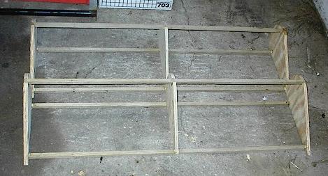
  Then cover'd them...


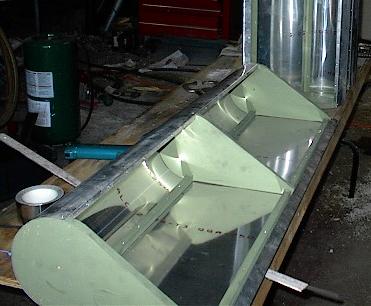
  I had some concerns about not using the discs on top and bottom and actually started making them out of plywood.  After drawing out the circle and seeing how much material it was going to use I decided on a lighter/stronger system.  I wasn't really sure if the discs helped funnel air through the wings, enhancing performance on the little one, or possibly hindering it a bit.  I wanted to know and I figured I could build a lightweight disc to add later if it didn't seem to work as well.  The main unit with the alternator weigh'd in at around 60 lbs.  The 6ft 1" solid steel shaft is 20 lbs of that weight.


  Below shows the finished unit mounted once again on the loader of my tractor.  Makes it easy to get it up in the air....


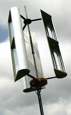
  Still not real windy we were getting between 2 and 12 mph.  I started as I did before sitting on the bucket watching the meters... amps, battery voltage, and wind speed.  I only spent an hour outside today and took 15 samplings while watching it run.  I must say I am impressed.  


  I used the same alternator that was on the small one so I was concerned about the cut in speed moving up to a 3 ft dia from the 2ft although I suspected the unit would over run a bit making up some of the differences.  I no more that put it in the air and it was spinning, the lowest reading on my wind meter was 1.5 mph she was running.  After a small treck to an open area where the air was moving freely things started getting fun.


  It starts charging in a 5.5 mph wind, almost the same as the small one.  At 6mph its doing 4.97 watts, at 8mph its running 13.3 watts and the highest reading at 12.5 mph she was doing 52 watts.   I'll let you do the math.  The average efficiency from the lowest wind to the highest was 36.5% of total area.  My reading in real low winds were low, I believe, because it was simply over running and hanging on the edge of charging which showed around 25% efficiency.  Its been sitting between two buildings out of the main wind with the clips locked together (shorted) and it has yet to stop spinning very very slowly.


  I guess its time to build another one... only bigger!  After this one is mounted of course....


.

« Last Edit: August 27, 2005, 06:03:31 PM by (unknown) »
Windstuff Ed

TomW

  • Super Hero Member Plus
  • *******
  • Posts: 5130
  • Country: us
Re: Lenz2 tests...
« Reply #1 on: August 27, 2005, 12:28:30 PM »
Ed;


As usual, darn fine bit of building! Been following your VAWT escapades right along because I always felt they got a bad rap along the line from often cited false information.


Cheers.


TomW

« Last Edit: August 27, 2005, 12:28:30 PM by TomW »

electrondady1

  • SuperHero Member
  • ******
  • Posts: 3122
  • Country: ca
Re: Lenz2 tests...
« Reply #2 on: August 27, 2005, 01:10:39 PM »
wow ed , you can really crank'em out, that a great looking mill, and man ! does it ever work.
« Last Edit: August 27, 2005, 01:10:39 PM by electrondady1 »

bparks

  • Newbie
  • *
  • Posts: 31
Re: Lenz2 tests...
« Reply #3 on: August 27, 2005, 02:10:14 PM »
Simply beautiful, and inspiring.  How big do you plan to make the next one?  I have a feeling there will be a lot of these built in the coming years.
« Last Edit: August 27, 2005, 02:10:14 PM by bparks »

hiker

  • Hero Member
  • *****
  • Posts: 1661
  • BIG DOG
Re: Lenz2 tests...
« Reply #4 on: August 27, 2005, 02:16:20 PM »
looks kinda cool thier windstuffnow.........


  remines me of my model airplane days--makin wings from blasa wood and putting the cloth over them..think i"le take a try at making a vawt--maybe use a tarp to cover the wings[canvas or plastic should work]..how much loss in rpm do you think you have with the  vacum the wings create on the back side of them?? if any at all..or does it help to make the wings spin faster..any ideas on using a geared up arrangment for the alt?

sence you said it still spins even when shorted out--seems like you would have plenty of tork to do this--and get higher volts output..[im sure you played with the idea].

« Last Edit: August 27, 2005, 02:16:20 PM by hiker »
WILD in ALASKA

windstuffnow

  • Hero Member
  • *****
  • Posts: 1065
  • Country: 00
Re: Lenz2 tests...
« Reply #5 on: August 27, 2005, 02:55:41 PM »
  I actually considered covering them in cloth.  I have a partial roll of stits and some odds and ends left over from covering some experimentals.  It would definately make the wings much lighter.  I would still cover the nose with some aluminum flashing to hold the shape as well as a stringer on the trailing edge although some tight wire would work fine.


   Quite simple to build !


.

« Last Edit: August 27, 2005, 02:55:41 PM by windstuffnow »
Windstuff Ed

MelTx

  • Full Member
  • ***
  • Posts: 127
Re: Lenz2 tests...
« Reply #6 on: August 27, 2005, 03:01:32 PM »


  Yeah things are starting to look up.Do the blades swivel on the arms that hold them to the main shaft or do stay fixed? Does this look like a good alterntive to carving blades.I wonder how high off the ground they need to be.
« Last Edit: August 27, 2005, 03:01:32 PM by MelTx »

windstuffnow

  • Hero Member
  • *****
  • Posts: 1065
  • Country: 00
Re: Lenz2 tests...
« Reply #7 on: August 27, 2005, 03:09:26 PM »
  Thanks all for the kind words.  For the next one I have my eye on some cardboard shipping drums that are 18" in diameter and stand about 29" tall.  I recieved them when I ordered some NOS 3kw generators and saved them for some odd project... I think I found a use for them.  This would make an 8ft diameter machine about 7ft tall with 39" long wings.  Could be interesting.  I doubt I'll have time to build it up this year but it sure sounds like a fun project in the near future.


  Oh, I forgot to mention... I built up a 2 bladed unit to test out... It was quite poor.  It produced 1/2 the power of the 3 blade.  After tinkering with it for a few hours I decided it simply wasn't worth the effort.


.

« Last Edit: August 27, 2005, 03:09:26 PM by windstuffnow »
Windstuff Ed

rotornuts

  • Hero Member
  • *****
  • Posts: 537
Re: Lenz2 tests...
« Reply #8 on: August 27, 2005, 03:44:32 PM »
You know Ed I have to like this. It has that big round lead edge that was trying to promote with my cylinder experiments. I'd like to try to build another with the flap on the inside like your's but leave the full cylinder in place rather than cut it in half. I think I'd probably experience the same result as when you covered the void in your previous experiments but never-the-less I'm curious. I have a bad habit of wanting to try the same things again and again till I'm good and sure I understand the reaction.


I did a crude wind test the other day of my helical design and I'm happy to say the rpm kept up nicely when I divered the air flow to the upwind side. I'm trying to lay low about it this time till I can actually report power production but I'll confess it's hard to contain one's enthusiasm for things one enjoys so much.


Mike

« Last Edit: August 27, 2005, 03:44:32 PM by rotornuts »

windstuffnow

  • Hero Member
  • *****
  • Posts: 1065
  • Country: 00
Re: Lenz2 tests...
« Reply #9 on: August 27, 2005, 05:36:00 PM »
  Now that sounds interesting... trying to envision the wind as it rotates... I'll bet it would work.


  I sort of became a bit tunnel visioned about the "C" type nose.  The split tube has the about the highest drag of any shape I've experimented with for the down wind side.  It carries a Cd of 2.31.  Unfortunately, on the upwind side it also carries a Cd of 1.1 ... just under 1/2.  By adding the tail it no longer see's it as a half tube and reduces the Cd to around .2 on the up wind side.   Add a good portion of lift and you have it.  


  Don't hold back !   I don't care if you don't have any numbers for it yet I like to see them in progress as well as the final result when it comes in.   I still haven't figured out how you did the twist on that machine... pretty cool stuff !


.

« Last Edit: August 27, 2005, 05:36:00 PM by windstuffnow »
Windstuff Ed

Devo

  • Full Member
  • ***
  • Posts: 175
Nice work!!
« Reply #10 on: August 27, 2005, 05:46:44 PM »
Top knotch Ed , can you make a drawing of the wood used to "Shape " the Aluminum & how far you wrap it around the nose?


 I would like to build one or two of those with some of that light wieght 8 thou aluminum I have.


I wonder what the result woud be if the upwind side was covered & that wind funneled

into the power side?  


Keep up the great posts!!


Devo

« Last Edit: August 27, 2005, 05:46:44 PM by Devo »

andrewdj

  • Newbie
  • *
  • Posts: 4
Re: Lenz2 tests...
« Reply #11 on: August 27, 2005, 07:22:07 PM »
   Wow ! I've been following your Lenz turbine experiments with a great interest.  I think it holds a lot of promise and you are Keeping me up at night studying the board.  Great work! Unlike the horzontal turbines, the problems of wind flow and the aerodynamics involved in a semi sav VAWT like this are very very complex and I suspect that you are right about the slower fatter airfoils for this type of machine.  I wish there were better ways to analyze the airflow patterns in a wind tunnel. Maybe smoke and a strobe or something. I liked the idea of checking the torque in 10 degree increments but I also suspect that when turning at different speeds,  there may be other, very unexpected patterns emerge.

I think I know the answer to why this wouldn't work but just out of curiosity did you ever try the "open" side of the wing on the inside as in one of your earlier idea drawings ?

I picture the outside "open" side of the wing as the top of an airplane airfoil.  In that case it seems that there should probably be a stall on the top of the wing where the airflow would "break away" on the open part of the "c" during that upwind leg especially.   What do you imagine is happening there ?   If it is, then the challenge might be to minimize this drag as much as possible on the upwind side.   Maybe a jagged edge on the outside back of the "c" edge ?  What about some amount of curve to the straight part of the wing ?  Instead of straight and flat.

What did you use for the crossarms on the new one ?

Please keep up the posts.
« Last Edit: August 27, 2005, 07:22:07 PM by andrewdj »

windstuffnow

  • Hero Member
  • *****
  • Posts: 1065
  • Country: 00
Re: Nice work!!
« Reply #12 on: August 27, 2005, 08:47:47 PM »
 Hi Devo,

    If your building it the same size, a 6.75" circle and a straight line from the tangent of the circle forms the wing shape.  Total length of the wing is 14.5 inches which includes the nose. Then simply draw a straight line from the trailing edge to the tangent of the circle for the open side.  I took a piece of treated lumber to make the stringers.  Ran them through the table saw making them 1/2" thick by 3/4" wide.  Notched the ribs to fit snug and glued them in place.  Bend the sheet to fit on the inside of the top stringer ( 1/2" ) and rivet it to the stringer using 1" long aluminum rivets.  I spaced them 3 inches appart.  Once its attatched its fairly easy to pull it around the nose and clamp it in place to run the next row of rivets on the next stringer untill it's all attatced.


  With aluminum that thin ( like flashing ), it will make a tinny noise as it rotates when the metal flexes and will cause fatigue fracturs over time.  You may want to coat the aluminum with some spray on undercoating or something similar to reduce the fatigue ( and noise ).   I'll see if I can come up with a drawing showing how the ribs are laid out.


.

« Last Edit: August 27, 2005, 08:47:47 PM by windstuffnow »
Windstuff Ed

windstuffnow

  • Hero Member
  • *****
  • Posts: 1065
  • Country: 00
Re: Lenz2 tests...
« Reply #13 on: August 27, 2005, 09:02:02 PM »
  When I did the locked rotor tests at 10 degree increments it was to get sort of a visual of what the wing was doing at that point.  I realize when its spinning at different rpm's there are suttle changes in the air flow.  It was also done with only one wing on the machine so there wasn't any interference from other wings on the back side of the tests.


  I'm sure there could be many changes made that might possibly enhance the output but at this point I'm pretty happy with the results.  I'm sure someone will change what I've done to bring it to another level.


  As far as the other wing designs on my site, I havent tried them as yet so I really don't know how well they would perform.  They were drawn as possibilities although the 1/2 circle with the center plate idea I believe will create more drag than you want on the upwind side.


Lots of fun!

.

« Last Edit: August 27, 2005, 09:02:02 PM by windstuffnow »
Windstuff Ed

bob g

  • Hero Member
  • *****
  • Posts: 1107
  • 8.8kwatt idi diesel thermal conversion unit
    • microcogen.info
Re: Lenz2 tests...
« Reply #14 on: August 27, 2005, 10:31:02 PM »
Ed


that thing is absolutely beautiful..


and it shines like a dime in a goats, well you know!


wow


i can't wait to see the larger version.


bob g

« Last Edit: August 27, 2005, 10:31:02 PM by bob g »
research and development of a S195 changfa based trigenerator, modified
large frame automotive alternators for high output/high efficiency project X alternator for 24, 48 and higher voltages, and related cogen components.
www.microcogen.info and a SOMRAD member

hiker

  • Hero Member
  • *****
  • Posts: 1661
  • BIG DOG
Re: Lenz2 tests...
« Reply #15 on: August 28, 2005, 02:11:08 AM »
just a thought ed..


 would it work any better with the airscoop side on the inside and the airfoil shape on the outside??

seems like it would speed up more but might have less tork.........

« Last Edit: August 28, 2005, 02:11:08 AM by hiker »
WILD in ALASKA

ZooT

  • Full Member
  • ***
  • Posts: 187
Re: Lenz2 tests...
« Reply #16 on: August 28, 2005, 09:20:36 PM »
Hey Ed, just a thought here: (bet you've heard that before 8^P)


Would there be any advantages to  mounting your "blades" on a pivot similiar to your darius design, and using eccentrics, change the angles of your blades on both the downwind blade and the blade that's being "pulled" into it's work position to extract a bit more power from those blades?


It seems that if you were to kick the trailing edge out on the downwind blade while pulling the trailing edge in on the blade being pulled to it's work position you could cause those two blades to produce more power.


But then again, I might not have any idea of what I'm talking about too, after all, I'm a newbie.......

« Last Edit: August 28, 2005, 09:20:36 PM by ZooT »

windstuffnow

  • Hero Member
  • *****
  • Posts: 1065
  • Country: 00
Re: Lenz2 tests...
« Reply #17 on: August 29, 2005, 11:26:53 AM »
  I had put some thought into making an articulated blade system for it and your right, if it was well worked out I believe you could squeeze some power out of it.  If the down wind blade moved outward, adding more area to the unit,but it's possible it might actually hinder its performance.


  Consider for a moment what is actually going on with the wings.  If the incomming air is moving at 11.5 mph and the machine is extracting power at a TSR of .8 ... what are wings actually seeing?


  Lets consider the downwind side firstly.  If the blade is moving at a TSR of .8 this means the blade is moving away from the wind at 9.2 mph so in reality your only collecting from a 2.3 mph wind... ( 11.5 - 9.2 ).  Any significant increase in rotor size won't make a lot of difference on the downwind side.


  Now, on the upwind side the blade is still moving at 9.2 mph but into the 11.5 mph wind or a total speed the wings sees is 20.7 mph so it only makes sense to collect as much as possible from that side of the turbine.  You could, however, articulate the upwind blade enough to enhance the amount of time it carries maximum lift which would definately help.


  Once you start thinking of what the two sides are actually doing it makes it easier to see what can be changed to make it better.  I chose not to articulate the blades in order to keep it simple.  At this point it performs well enough to continue developing the basic unit.  I'll get bored with it soon enough and will attempt other changes as time goes on.


  There is a point to any project which it becomes more expensive, elaborate or difficult to eek out fractions of increases.  Similar to building a race engine.  You can do alot of cheap things to a stock engine to get major power increases,  beyond that things start getting more expensive for smaller gains.  You simply need to weigh the benifits over the cost or in this case the intricate workings of a cam/tail based system... could I get 2 more watts out of it? sure I could !  Would it be worth the extra labor and complexity?   not sure.


.

« Last Edit: August 29, 2005, 11:26:53 AM by windstuffnow »
Windstuff Ed

MountainMan

  • Full Member
  • ***
  • Posts: 138
Re: Lenz2 tests...
« Reply #18 on: August 29, 2005, 07:12:40 PM »
I don't think the subject of "furling" has come up much in your VAWT escapades.  What do you do with a VAWT when it's destructively windy?  Does a VAWT have some sort of a self protection mechanism that is lacking in a HAWT?  Or is it just that the typical speed of a VAWT is lower, so an 80mph wind doesn't get it up to a damaging speed? ...or do you just tilt the bucket of the tractor down to get it out of the wind?  :)


thanks,

jp

« Last Edit: August 29, 2005, 07:12:40 PM by MountainMan »

windstuffnow

  • Hero Member
  • *****
  • Posts: 1065
  • Country: 00
Re: Lenz2 tests...
« Reply #19 on: August 29, 2005, 09:58:27 PM »
  Pretty funny jp,  you know as funny as that sounds thats actually a start to a good idea.  On the lighter side, if we have destructive winds the wind turbines are the last thing I'm worried about.  I can replace them easy enough.


  I simply short the stator and hope it makes it for the most part.  As long as the tower or stand is strong enough the turbine will spin slowly with a shorted stator.   My sav never had anything, I simply let it go, it survived several 60+ mph storms.  I always thought, watching it, that it was going to come off the bearings or tear down the frame.  Next morning its still spinning along like nothing happened.  Dig the leaves and sticks out of the vanes get it back in balance.

.  

« Last Edit: August 29, 2005, 09:58:27 PM by windstuffnow »
Windstuff Ed

SparWeb

  • Global Moderator
  • Super Hero Member Plus
  • *****
  • Posts: 5448
  • Country: ca
    • Wind Turbine Project Field Notes
Re: Lenz2 tests...
« Reply #20 on: August 31, 2005, 01:55:27 PM »
Wow,


Neat stuff.  I just joined, and all along I thought I was the only loonie building these things.  I'm not quite as far along as you are, but working on my third Darrieus-type turbine.


Will you be incorporating the pitch-change cams into your Lenz turbines?

« Last Edit: August 31, 2005, 01:55:27 PM by SparWeb »
No one believes the theory except the one who developed it. Everyone believes the experiment except the one who ran it.
System spec: 135w BP multicrystalline panels, Xantrex C40, DIY 10ft (3m) diameter wind turbine, Tri-Star TS60, 800AH x 24V AGM Battery, Xantrex SW4024
www.sparweb.ca