Author Topic: 12V fluoro inverter  (Read 7152 times)

0 Members and 1 Guest are viewing this topic.

BT Humble

  • Sr. Member
  • ****
  • Posts: 475
12V fluoro inverter
« on: January 31, 2005, 11:41:16 PM »
To give credit where it's due, I borrowed the circuit from here:


http://www.aaroncake.net/circuits/40wflamp.htm


To build the circuit as I've constructed it, you'll need:


  • 50mm piece of 10mm ferrite rod;
  • 0.6mm enamelled wire;
  • 0.4mm enamelled wire;
  • TIP31C transistor (or any other type that will handle 3A);
  • 100uF 16V electrolytic capacitor;
  • 0.1uF (100nF) polyester or ceramic capacitor;
  • 180 ohm 1W resistor;
  • 47 ohm 1/4W resistor;
  • 1N5408 diode (or equivalent 3A type);
  • 30x70mm blank PCB.


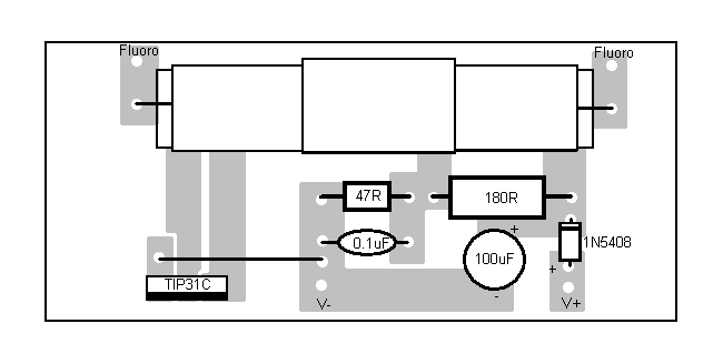
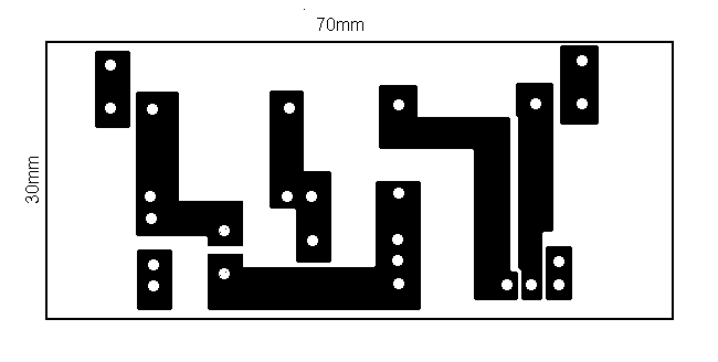
Here's the artwork and circuit overlay for the PCB:


To construct the coil, first insulate the ferrite rod with a couple of strips of masking tape.  Next, wind 90 turns of 0.4mm enamelled wire onto it.  This should be a neat fit if you start 5mm from one end.  Secure and insulate this layer with strips of masking tape.  Continue winding in the same direction (ie. don't reverse the direction of your turns) to form a second layer over the top of the first, then secure and insulate it with masking tape as well.  Continue until you have 5 layers.  This coil will be the secondary.


Next, wind 52 turns of 0.6mm wire onto the ferrite, securing the coil as before.  This coil will be the Primary.


Finally, wind 12 turns of 0.6mm wire onto the ferrite in the opposite direction to how you wound the primary.  Secure with masking tape as before.  This coil will be the feedback.  You should now have a completed transformer would on the ferrite that looks like this:
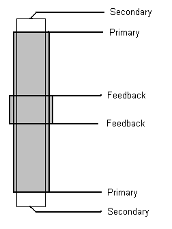


This will neatly slot into the row of 6 holes on the PCB.  Connect to a 12V supply and a fluorescent tube, and it should work.  For a 20W tube increase the value of the 0.1uF capacitor to 0.47uF or so.  This technique can also be used to decrease the current consumption and brightness to whatever level you find acceptable.


Enjoy!


BTH

« Last Edit: January 31, 2005, 11:41:16 PM by (unknown) »

ghurd

  • Super Hero Member Plus
  • *******
  • Posts: 8059
Re: 12V fluoro inverter
« Reply #1 on: January 31, 2005, 04:49:20 PM »
Yes!  Thanks!

G-
« Last Edit: January 31, 2005, 04:49:20 PM by ghurd »
www.ghurd.info<<<-----Information on my Controller

deerslayer660

  • Newbie
  • *
  • Posts: 37
Re: 12V fluoro inverter
« Reply #2 on: January 31, 2005, 06:10:35 PM »
thanks ? how far can curcuit be from tube george
« Last Edit: January 31, 2005, 06:10:35 PM by deerslayer660 »

whatsnext

  • Sr. Member
  • ****
  • Posts: 449
Re: 12V fluoro inverter
« Reply #3 on: January 31, 2005, 07:20:33 PM »
BT, Yes thank you. Do you know if anyone would want to build a board?

John.....
« Last Edit: January 31, 2005, 07:20:33 PM by whatsnext »

BT Humble

  • Sr. Member
  • ****
  • Posts: 475
Re: 12V fluoro inverter
« Reply #4 on: January 31, 2005, 08:24:25 PM »


BT, Yes thank you. Do you know if anyone would want to build a board?

John.....


Should I take that as a "How do I go about making my own PCB?" ;-)


It's pretty straightforward, and once you have the $20 worth of equipment it's a lot cheaper that using those prototyping strip boards.


BTH

« Last Edit: January 31, 2005, 08:24:25 PM by BT Humble »

BT Humble

  • Sr. Member
  • ****
  • Posts: 475
Re: 12V fluoro inverter
« Reply #5 on: April 05, 2005, 03:59:09 PM »


thanks ? how far can curcuit be from tube george


I usually build the inverter into the fitting that holds the tube, since there's a slightly greater chance of getting an electric shock from the output of this (~100VAC) than from the 12VDC supply.  Technically I think you'd be able to locate the tube a substantial distance away, although I can't really see why you'd want to?


BTH

(Sorry for the 2-months-late reply!)

« Last Edit: April 05, 2005, 03:59:09 PM by BT Humble »

Reddwarf

  • Newbie
  • *
  • Posts: 1
Re: 12V fluoro inverter
« Reply #6 on: September 07, 2008, 10:28:46 AM »
I want to build an electronic ballast for 5 40W tubes based on your design and run it on 320V DC, ie rectified 230V AC. What components should be changed and to what value? Can I use a 13003 transistor, obviously tha 3055 can not be used.

Thanks in advance.
« Last Edit: September 07, 2008, 10:28:46 AM by Reddwarf »