Author Topic: Blade Layout  (Read 2986 times)

0 Members and 1 Guest are viewing this topic.

Bigwheel

  • Jr. Member
  • **
  • Posts: 55
Blade Layout
« on: November 12, 2008, 09:22:50 PM »
Hi again, As I stated before, I'm in the process of builing a 10 footer and have come to the last challenge of building the blades.  I have went over and over the autocad prints that DanB has put out there to share.  Thanks for the layouts, But I'm lost or do I need to change the orientation of the view to get things to work out.  First and formost here's where I stand.  I have copied the plans to the tee, when looking directly from the front( blade side), the blades are turning in a counter clock wise direction? If so, then the leading edge would be the first thing to touch my finger off if the rotation is correct.  If I were to be looking down at the outer diameter (5" radius) what does the blade profile look like from this angle??  I'm thinking the radial profile of the back side of the blade is backwards based on the drawings.  My fear is that I will carve these up and it will spin counter-clockwise and cancel out the genny's ability to furl.  I guess you could say I'm stumped on this one after countless hours of debating I figure it's best to ask if someone might have a endview picture.  I just don't know what to say!!  Maybe just need a better explination that will turn on the lights!!  Sorry to bother and Thanks for the help chad
« Last Edit: November 12, 2008, 09:22:50 PM by (unknown) »

la7qz

  • Full Member
  • ***
  • Posts: 115
Re: Blade Layout
« Reply #1 on: November 12, 2008, 03:14:22 PM »
Hi


I'm not sure exactly what you're asking here, but the blades on a wind turbine look "backwards" as compared to the blades on an aircraft propeller. You are taking energy from the wind, rather than putting energy into the air.


I know this has confused quite a few of the fellow sailors I've installed wind generators for. In one case, I had to take the guy on a dinghy trip around the anchorage to look at half a dozen other turbines before he would believe me. Thankfully, it was a windless day.


Owen

« Last Edit: November 12, 2008, 03:14:22 PM by la7qz »

Ungrounded Lightning Rod

  • SuperHero Member
  • ******
  • Posts: 2865
Re: Blade Layout
« Reply #2 on: November 12, 2008, 03:22:29 PM »
The rounded edge is the one that hits your finger and the humped side is downwind.


The former is the same as a propeller and the latter is the opposite of a propeller.

« Last Edit: November 12, 2008, 03:22:29 PM by Ungrounded Lightning Rod »

Ungrounded Lightning Rod

  • SuperHero Member
  • ******
  • Posts: 2865
Re: Blade Layout
« Reply #3 on: November 12, 2008, 03:29:47 PM »
Next time you're talking to a sailor about it, tell him that each blade is a little sail, sailing around the axle on a broad reach.  Then ask him to think about how the downwind side of the sail is convex so you can keep the air attached to it and get lift that propels the boat - or the blade - forward.


You'll still have to tell him about it being deliberately convex on the opposite side from the way a propeller is arranged because it want to slow the wind down (taking power from it) rather than speed it up (putting power into it).  In fact you'll want to tell him that first.  But perhaps the sail analogy will help convince him.

« Last Edit: November 12, 2008, 03:29:47 PM by Ungrounded Lightning Rod »

SparWeb

  • Global Moderator
  • Super Hero Member Plus
  • *****
  • Posts: 5452
  • Country: ca
    • Wind Turbine Project Field Notes
Re: Blade Layout
« Reply #4 on: November 12, 2008, 04:02:14 PM »
You would be less mixed up if you imagine the finished prop and work your way toward the details from there.

Let's say it's a 3-blade prop.  All 3 must be identical.  If you are facing a fully assembled windmill prop, then you can't see much of the alternator behind it, because the thick root of the blades cover most of it.  Each blade (should) taper as you look at the tips.  The face you are looking at is basicaly all flat planes.  The wind is at your back, and the side of the blade you can see is the "bottom" of the airfoil.  The other side of the blades has much more curvature - that is the "top" of the airfoil.

Walk around to look at the prop edge on.  Now you can see the leading edge (blunt) and trailing edge (sharp).  The blade inclines the leading edge slightly forward, but mostly it points in the direction of rotation.  If the blade was made with any twist, then it will be obvious from here.  The tip points almost exactly in the direction of rotation, but at the root the angle is more like 30 degrees.  


Here's a graphic looking at the tip of a blade:


The wind blows from the top to the bottom of the diagram.  Lift points down, and the blade moves to the left.  The red line is a straight trailing edge, which works fine and I think that's how the Otherpower blades are made.  The airfoils in the diagram were drawn with a "theoretical" ideal twist, which was part of some previous discussion long ago, so the trailing edge could be curved, if you want.  Hopefully it serves the purpose of illustration.


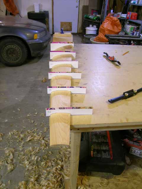
Here's one of my blades after carving:


« Last Edit: November 12, 2008, 04:02:14 PM by SparWeb »
No one believes the theory except the one who developed it. Everyone believes the experiment except the one who ran it.
System spec: 135w BP multicrystalline panels, Xantrex C40, DIY 10ft (3m) diameter wind turbine, Tri-Star TS60, 800AH x 24V AGM Battery, Xantrex SW4024
www.sparweb.ca

Bigwheel

  • Jr. Member
  • **
  • Posts: 55
Re: Blade Layout
« Reply #5 on: November 12, 2008, 04:09:56 PM »
"The rounded edge is the one that hits your finger and the humped side is downwind"

So based on what you have stated, when looking head on at the turbine the blades are spinning counter clockwise and the trailing edge is going to hit my finger first?  I understand the hump is on the back side. The problem I am having is when I look at the autocad drawing that Dan has in the building page of the 10 footer the fifth picture is the one throwing me for the loop.  After looking at the pictures in the assembly section and refering to the drawing, I was thinking the dark portion is what you need to remove.  In my mind the two views should be flip flopped. At least that what I learned in drafting class, the dark on the bottom view would be hidden.  Tell me If I'm wrong.  Back to the building section, Take the last drawing for example, looking down the blade from the center of the axis this is what I would be seeing correct?  Let me know if I'm on the right track.  Thanks again for the input  Chad  
« Last Edit: November 12, 2008, 04:09:56 PM by Bigwheel »

imsmooth

  • Sr. Member
  • ****
  • Posts: 425
Re: Blade Layout
« Reply #6 on: November 12, 2008, 06:45:50 PM »
Steve,


Isn't the trailing edge on the side facing the wind suppose to drop as you get closer to the root?  It looks like your windside never drops; only the side away from the wind is dropping.

« Last Edit: November 12, 2008, 06:45:50 PM by imsmooth »

Ungrounded Lightning Rod

  • SuperHero Member
  • ******
  • Posts: 2865
Re: Blade Layout
« Reply #7 on: November 12, 2008, 07:10:29 PM »
The leading edge will always be the one that hits your fingers when the device is rotating normally.  That's why it's "leading".


(I assumed it was being spun by wind or you'd looked at the chord angle and imagined which way it would turn when the wind is hitting it.  I don't have those drawings to look at.  So "which side hits my finger if I spin it clockwise while looking at it from windward" or whatever isn't something I can make heads or tails of from here.)


Leading edge is the rounded one.  This is so the wind will "attach" to it from a range of angles of attack - accepting some drag to make this happen.  (The angle of attack changes with the ratio of the wind speed to the rotation speed, making it vary with both load and changes in wind speed.  So you need a range of attachment angles to keep the blade from stalling.)


Trailing edge is narrow and sharp.  This lets the airflows from the two sides join and depart in a well defined direction, with a minimum of drag and negligible turbulence.


Mainsails do something close to this, with the mast providing the rounded leading edge and the luff (rear) edge of the sail providing a sharp trailing edge.

« Last Edit: November 12, 2008, 07:10:29 PM by Ungrounded Lightning Rod »

Bigwheel

  • Jr. Member
  • **
  • Posts: 55
Re: Blade Layout
« Reply #8 on: November 12, 2008, 08:32:08 PM »
What I will try and do tonight at work is draw up a hand sketch and see if i understand the concept.  I guess I just more of a visual minded person and a picture is worth a thousand words.  I'll see what I can come up with and hopefully i can scan it in and it be small enough to post.  Thanks chad
« Last Edit: November 12, 2008, 08:32:08 PM by Bigwheel »

Ungrounded Lightning Rod

  • SuperHero Member
  • ******
  • Posts: 2865
Re: Blade Layout
« Reply #9 on: November 12, 2008, 09:13:28 PM »
The trailing edge doesn't face the wind.  At any point along a HAWT-style blade the leading edge is pointed a bit toward the wind and the trailing edge is pointed a bit away from it.


But because the blade moves primarily crosswind, the chord - a line through the blade between the leading and trailing edges - is ALMOST at right angles to the wind.


As you get near the root the angle of the chord changes ("twists"), so the leading edge points more toward the wind and the trailing edge more away from it.  This is because the component of the "apparent wind" from the blade's motion reduces as you get near the center, but the component from the real wind is always (essentially) the same.  If the twist continued all the way to the center of the shaft the leading edge would be pointed straight upwind and the trailing edge straight downwind.

« Last Edit: November 12, 2008, 09:13:28 PM by Ungrounded Lightning Rod »

Capt Slog

  • Sr. Member
  • ****
  • Posts: 378
Re: Blade Layout
« Reply #10 on: November 13, 2008, 04:27:46 AM »
ULR.


"But because the blade moves primarily crosswind, the chord - a line through the blade between the leading and trailing edges - is ALMOST at right angles to the wind."


On blade calculators you see 'angle of attack'.  Is that the angle they refer to?  The one I have puts 4 degrees as the AOA as a default value.


Ta


.

« Last Edit: November 13, 2008, 04:27:46 AM by Capt Slog »

Flux

  • Super Hero Member Plus
  • *******
  • Posts: 6275
Re: Blade Layout
« Reply #11 on: November 13, 2008, 11:39:35 AM »
If you are copying the Otherpower blades then as far as I know the rotation is clockwise looking at it from upwind.

looking at the marked out board of a blade at the top of its travel the uncut edge of the flat driving face ( which you will be looking at)with the rounded section going to the back will be the the leading edge.


The bit that you have to cut away on the Lhs will be the trailing edge and that will slope away from the rhs at about 3 deg at the tip. The back curved surface will be such that it meets the trailing edge at a sharp angle.


If you want to reverse the rotation you have to flip everything so that the rhs and lhs interchange.


You had better check but most props are clockwise rotation looking from upwind and I doubt that this is different.


See if this helps. This is a simple 2 blade prop and if you look at the top half of the blade from the flat side it will rotate clockwise. the rhs is the leading edge.


Normally the back surface is such that the leading edge is rounded not sharp as in this case. the trailing edge is normal.


Flux

« Last Edit: November 13, 2008, 11:39:35 AM by Flux »

Bigwheel

  • Jr. Member
  • **
  • Posts: 55
Re: Blade Layout
« Reply #12 on: November 13, 2008, 12:28:12 PM »
Hi, this is what I have been looking for.  Thanks, though I did sketch something up last night and then I remembered seeing a couple of pictures on the Back shed a long time ago.  I going to borrow the pictures and post them for my clarity and maybe someone elses.  My biggest fear was carving up a set and have them spin the wrong way and then the machine wouldn't furl properly.  Here's a top view pic of the blade and the clock wise direction it will spin in.


Well not a very clear picture so here's a link to the page about there blades

http://www.thebackshed.com/Windmill/PropellerBlades.asp

Like I mentioned before about making sure the blades rotated in the proper direction, here's a picture showing the clock wise direction and direction in which is will furl.  The same way the machine needs to furl like that in the building page.  


Also not a real clear picture but here's the link to the page that discusses furling.

http://www.thebackshed.com/Windmill/Docs/Furling.asp

So up to this point I think I have a decent grasp on the blade carving and just need to take my time and lay everything out so it comes out correctly.  That way I'm not walking around in circles.  Time to make some jigs and ruff things in.  Thanks again for the help and guidence Chad
« Last Edit: November 13, 2008, 12:28:12 PM by Bigwheel »

Capt Slog

  • Sr. Member
  • ****
  • Posts: 378
Re: Blade Layout
« Reply #13 on: November 14, 2008, 08:21:25 AM »
"My biggest fear was carving up a set and have them spin the wrong way and then the machine wouldn't furl properly. "


I can't see how it makes any difference.  The force of the wind that pushes the blades around the offset is not affected by which way they are spinning, to the wind they are just a disc in this case.


,

« Last Edit: November 14, 2008, 08:21:25 AM by Capt Slog »